Table of Contents
Advertisement
Quick Links
Advertisement
Table of Contents

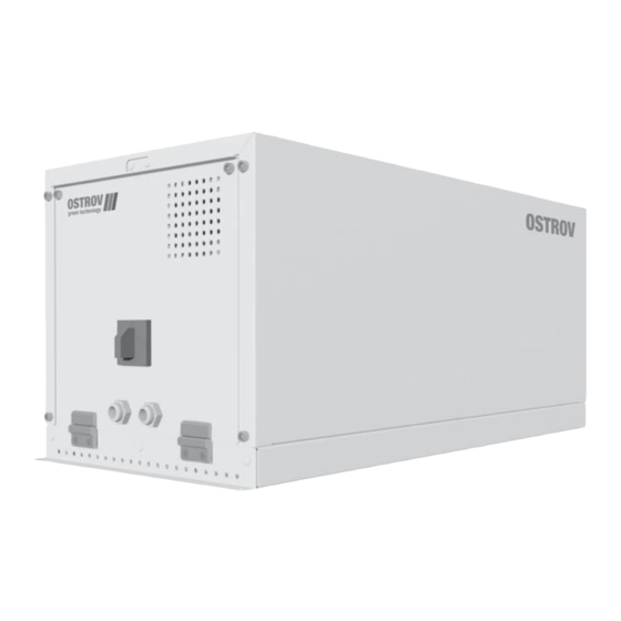
Summary of Contents for OSTROV OA331
- Page 1 CONDENSING UNITS OA331 Operating Instructions...
-
Page 2: Table Of Contents
Table of contents Introduction 1 Terms and defi nitions 2 General information 3 Areas of responsibility 3.1 Manufacturer’s responsibilities 3.2 System installer’s responsibilities 3.3 Owner or operator responsibilities 4 General information on safety requirements 4.1 Safety of the refrigeration system 4.2 Safety signs... - Page 3 11 Operation 12 Shutdown 13 Maintenance 14 Decommissioning for a prolonged period 15 Decommissioning and disposal 16 Declaration of conformity Appendix 1. Requirements for heat transfer fl uids for chilled water loop...
-
Page 4: Introduction
Introduction These operating instructions contain important information on installation, use and maintenance of OSTROV OA331 condensing units (hereinafter referred to as the units). Please read the instructions carefully before operating the equipment and keep them in the unit’s immediate vicinity during its entire lifetime. -
Page 5: Terms And Defi Nitions
(when required) and the regularly furnished accessories. 2 General Information OSTROV OA331 condensing units (hereinafter referred to as the units) are completely factory-assembled and built in compliance with current international and national standards in the specifi c fi eld of refrigeration systems. -
Page 6: Areas Of Responsibility
The scope of delivery includes the following documents: operating instructions; piping and instrumentation diagram; wiring diagram; EU Declaration of Conformity – ostrov.com. 3 Areas of responsibility 3.1 Manufacturer’s responsibilities The responsibility of the manufacturer extends to the delivered condensing unit only. -
Page 7: System Installer's Responsibilities
3.2 System installer’s responsibilities 3.3 Owner or operator responsibilities The responsibility of the owner or operator includes operation, The system installer’s responsibility includes designing, maintenance, servicing and recovery of the refrigeration system manufacturing and testing the refrigeration system according... -
Page 8: General Information On Safety Requirements
After having fi nished the work, do not leave 4 General information on safety requirements any foreign objects inside the unit as they may cause damage to the fans and/or the 4.1 Safety of the refrigeration system unit after reactivation. - Page 9 Even after the unit is turned off , voltage 8-hour working day and a 40-hour working week. remains at inputs of the control cable and the This average concentration is greater than or power supply cable as well as on the terminal equal to 400 ml/m³.
-
Page 10: Personal Protective Equipment
4.5 Personal protective equipment the Assembly Organization, the Owner and the Operating Organization. In accordance with EN 378-3, personal protective equipment is required to protect personnel. Individual protective Summary of the personal protective equipment to be equipment must be ready for use and stored in a place used throughout the life of the unit is shown in the accessible to the personnel. -
Page 11: Packaging
5 Packaging The units are covered with polyethylene fi lm against atmospheric eff ects. Upon the client’s request, the units may be supplied mounted on a wooden pallet inside a wooden crate in order to avoid transport damage (Fig. 5.1). -
Page 12: Transportation
(Fig. 7.2). Fig. 7.2 If you have any doubts about the proper transportation method, please contact Ostrov. In case of lifting the unit by crane, use only slings corresponding to the type and weight of the transported load. -
Page 13: Placement
8 Placement The units are designed for indoor placement. The units can be installed in machinery rooms, in technical rooms, in general-purpose rooms, as well as directly on the housing of consumer of cold. It is recommended to place the units in accordance with the... -
Page 14: Check The Factory Pressure
2. Remove the fasteners of the wooden frame (Fig. 9.3). 3. Remove the wooden frame. 4. Remove the protective fi lm. 5. Check the contents of the packaging for completeness. 6. Check the unit for damage. Fig. 9.3 9.2 Check the factory pressure Check the excess pressure. -
Page 15: Connection Of Pipelines Of Refrigerant Circuit
The unit has two nozzles for threaded connection. The connecting dimensions are given in the technical catalog and the catalog sheet on the OA331 unit at ostrov.com. 1. It is recommended to connect pipelines to the unit in 6. Secure the pipelines on supporting structures. The... -
Page 16: Commissioning
10.3 Vacuum procedure 10 Commissioning Evacuate the system to remove any moisture or air. A Do not leave the unit unattended until the vacuum pump must be used for the evacuation. system has reached normal operating Never use the compressor to evacuate the system or start conditions. -
Page 17: Changing The Chilled Water Loop
After the start-up of the unit, the following must be checked: • The value of the starting currents of the compressor. Starting currents are indicated on the assembly compressor nameplate and in the OA331 technical catalog on ostrov.com. • Check that the suction pressure drops and the discharge pressure rises. -
Page 18: Check After The Unit Is Operational
10.7 Check after the unit is operational After the unit has reached normal operating conditions, perform the following checks: • Ensure that there are no extraneous noises and abnormal vibrations. • Check the refrigerant level. Сheck is performed according to the value of supercooling liquid refrigerant and superheated suction gas. -
Page 19: Shutdown
12 Shutdown In order to perform a normal shutdown of the unit, carry out the following: 1. Stop the operation of the unit by the control system. The compressor and pump will stop automatically. 2. Turn off power (Fig. 12.1). - Page 20 Maintenance checklist m - monthly, y – once a year Interval Maintenance work Visual inspection of unit for dirt deposits, rust and mechanical damage. Unit components and pipelines. Check and tightening of screw connections and fastenings to frame. Check pipelines for leaks.
-
Page 21: Decommissioning For A Prolonged Period
14 Decommissioning for a prolonged period 1. Close the shut-off valve on the liquid line on the body of the unit. 2. Wait until the low pressure switch stops the compressor. 3. Close the shut-off valve on the suction line on the unit housing. -
Page 22: Decommissioning And Disposal
fl uid in accordance with the regulations in force in the country where the unit is installed. 16 Declaration of conformity We hereby declare that the OSTROV OA331 condensing units comply with the following directives: • pressure Equipment Directive 2014/68/EU;... -
Page 23: Appendix 1. Requirements For Heat Transfer Fl Uids For Chilled Water Loop
Appendix 1. Requirements for heat transfer fl uids for chilled water loop As the heat transfer fl uid of the chilled water loop, aqueous solutions of glycol are used. The percentage of glycol is determined by the project. Water should be of drinking quality. - Page 24 European Union Ringhoff erova 115/1, 15521 Praha 5, Czech Republic tel.: +420 234 252 223 fax: +420 234 252 225 infocz@ostrov.com Russia and CIS 6, 2nd Bakuninsky Alleyway, Mytishchi Moscow Region, 141011, Russia tel.: +7 495 582 44 44 fax: +7 495 582 44 45...
Need help?
Do you have a question about the OA331 and is the answer not in the manual?
Questions and answers