Advertisement
Quick Links
1. Check if the aircraft parts and accessories in the box are complete
Check whether the carbon rods, carbon chips, and accessories are complete.
If the accessories are missing, please contact the manufacturer in time.
Speci cation:
0.5X4mm carbon chip 1 piece
0.2X3mm carbon sheets 6 pcs
1.0mm carbon rods 6 pcs
2.0X220mm carbon rods 2 pcs
Foam glue 1 pcs
Advertisement

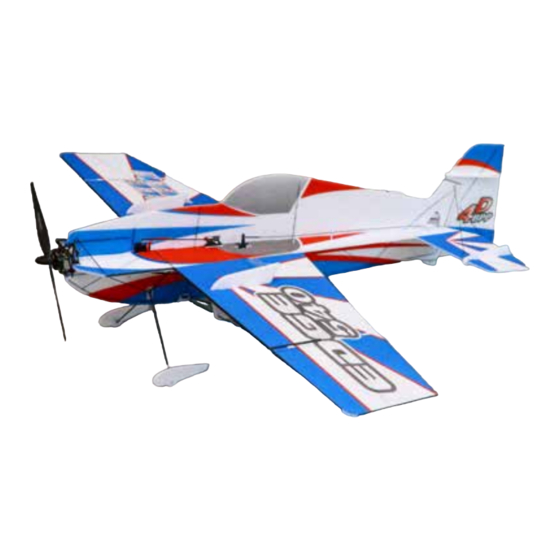
Summary of Contents for JADE TEAM EDGE540
- Page 1 1. Check if the aircraft parts and accessories in the box are complete Check whether the carbon rods, carbon chips, and accessories are complete. If the accessories are missing, please contact the manufacturer in time. Speci cation: 0.5X4mm carbon chip 1 piece 0.2X3mm carbon sheets 6 pcs 1.0mm carbon rods 6 pcs 2.0X220mm carbon rods 2 pcs...
- Page 2 2. Use heavy objects to press each rudder surface for 1-2 hours 3. Glue the horizontal plane of the fuselage and the at tail, prepare a ruler and a marker, use the ruler to align the tenon in the middle of the fuselage and mark the left and right sides with a marker.
- Page 4 After the bonding is completed, use a utility knife to cut along the slot of the cut carbon sheet again (do not cut through the sheet) to make the carbon sheet smoothly embedded.
- Page 5 4. Glue the horizontal plane of the fuselage and the left and right wings, use a marker to mark the dummy assembly of the wing and apply glue on both sides of the bonding surface after the dummy assembly is correct...
- Page 6 5. Take out the 0.5X4mm carbon sheet from the carbon ber package. The bonding surface of the carbon sheet and the board needs to be glued to the front carbon sheet of the wing.
- Page 7 6. Install the carbon sheet of the machine head, take out the 0.2X3mm carbon sheet from the package, cut the carbon sheet to an appropriate length and insert it into the cut slot to x it with 502 glue. As EPP is permeable, please pay attention to the amount of 502 glue.
- Page 8 After the carbon sheet is xed, use a ruler and a marker to bond the head and the body 7. Install the horizontal tail wing carbon sheet, use 0.2X3mm carbon sheet, the installation method is the same as above 8. The main wing is strengthened. Use 0.2X3mm carbon sheet. The installation method is the same as above.
- Page 9 9. Reinforced on both sides of the fuselage...
- Page 10 At this point, the installation and reinforcement of the horizontal fuselage is over. 10. Install the fuselage and the rudder surface carbon sheet, take out the vertical fuselage and use 0.2X3mm carbon sheet...
- Page 11 Here is a special note : to install this carbon sheet, the rudder surface must be set on the fuselage, and enough length is reserved for the installation of the carbon sheet.
- Page 12 Note: The carbon sheet in the above 3 pictures is bonded to the board, only the upper half of the body is bonded, and the lower half of the body is not bonded! So far, the aircraft’s built-in reinforcement has been fully completed. 11.
- Page 15 12. Install the main wing and aileron reinforcement sheet, refer to the picture and apply glue for bonding...
- Page 16 13. Install the landing gear, take out the accessories in the picture, and use 2X220mm carbon rods...
- Page 19 14. The fuselage and wing carbon rods are strengthened...
- Page 22 So far, the installation of the lower part of the fuselage has been completed. 15. Installation of rudder angle and electronic equipment...
- Page 23 Note: The steering gear with groove in the picture above is the elevator angle, and the connecting rod of the elevator surface has been reserved in advance, please nd it by yourself...
- Page 28 Note : The above accessories are used for the steering gear without the extended rocker arm. 16. Install the upper fuselage, and make a fake set of the upper fuselage and the aircraft. After the fake set is correct, glue and bond...
- Page 30 Note: The rudder surface tie rod has reserved holes, please look it up carefully. 17. Wing knife installation...
- Page 32 18. Install the motor base to the corresponding position of the nose. This aircraft can install the vector motor base. For the installation method of the vector motor base, please read the vector motor base manual •...
- Page 33 The center of gravity of the aircraft is 220mm behind the nose (excluding the motor). Thank you for your support to JADE TEAM products, and wish you a happy ight...
Need help?
Do you have a question about the EDGE540 and is the answer not in the manual?
Questions and answers