
Related Manuals for TRUWEO TRU010005N

Summary of Contents for TRUWEO TRU010005N
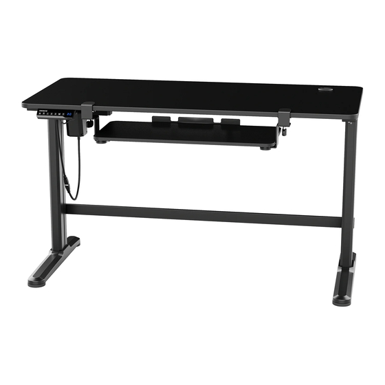
- Page 1 ELECTRIC STANDING DESK DESKTOP YEAR WARRANTY NEED TO SPEAK TO A DESK EXPERT? 1 (347) 841-0317 · support@truweo.com...
- Page 2 Failure to keep the product in its original quality from the time of receipt may impede TRUWEO’s ability to correct any legitimate problem and may limit the extent to which TRUWEO may provide recourse. NEED TO SPEAK TO A DESK EXPERT? 1 (347) 841-0317 ·...
-
Page 4: Table Of Contents
TABLE OF CONTENTS IMPORTANT SAFETY INFORMATION LIST OF PARTS ASSEMBLY INSTRUCTIONS OPERATION TROUBLESHOOTING CLEANING AND MAINTENANCE WARRANTY CONTACT US... -
Page 5: Important Safety Information
IMPORTANT SAFETY INFORMATION WARNING! IMPORTANT SAFETY INSTRUCTIONS! SAVE THESE INSTRUCTIONS! • Basic safety precautions should always be followed. PLEASE READ ALL INSTRUCTIONS BEFORE USING YOUR ELECTRIC STANDING DESK. DANGER To reduce the risk of electrical shock: • Always unplug this unit from the electrical outlet before cleaning. Risk of suffocation! •... - Page 6 FCC STATEMENT This device complies with part 15 of the FCC Rules. Operation is subject to the following two conditions: (1) this device may not cause harmful interference, and (2) this device must accept any interference received, including interference that may cause undesired operation.
-
Page 7: List Of Parts
LIST OF PARTS Count and inspect all parts before assembly. If anything is missing or damaged, please contact us immediately for a quick and free replacement: support@truweo.com × 1 × 1 × 2 Connecting Bar Motor Lifting Column (Column to Motor) ×... - Page 8 LIST OF PARTS × 4 × 4 × 6 Hex Head Screw Hex Head Screw Phillips Head Screw × 2 × 4 × 6 Phillips Head Screw Phillips Head Screw Washer (For the Controller) × 3 × 9 × 1 Cable Clip Silicone Pad 4 mm Allen Wrench...
- Page 9 LIST OF PARTS Desktop Side Bracket Connecting Bar Motor Controller Sync Rod (Column to Motor) Lifting Column Keyboard Tray Mounting Clamp Crossbar...
-
Page 10: Assembly Instructions
ASSEMBLY INSTRUCTIONS Prepare the Lifting Columns Lifting Column × 2 • Prepare an area with adequate space for installation. Put a blanket on the area to prevent scratches to the floor and the desk. • Remove the two screws on the top of the Lifting Columns (C) using the Phillips Phillips Screwdriver Screwdriver (S-L). -
Page 11: S-M
ASSEMBLY INSTRUCTIONS Attach the Side Brackets 4 mm Allen Wrench • Attach the Side Brackets (L) to the left and right Lifting Columns using 4 Screws (S-M). Make sure the longer end of the Side Brackets is facing Hex Head Screw × 4 toward the front of the desk and in the same direction as the lifting column. -
Page 12: S-H
ASSEMBLY INSTRUCTIONS Attach the Motor to the Lifting Columns Connecting Bar • Attach three Silicone Pads (S-H) to each Left Right Side Bracket on the Lifting Columns. • Insert the left end of Connecting Bar(A) to Motor the hex socket shaped mounting hole on the Lifting Column(C). - Page 13 ASSEMBLY INSTRUCTIONS Assemble the Adapter Holder (G) and the Crossbar (F) Crossbar • Attach 3 Silicone Pads (S-H) to the crossbar. Ensure that the side with the pads is facing against the desktop. Adapter Holder • Attach the Crossbar (F) to the two assembled lifting columns and tighten the Screws (S-B) using the 4 mm Allen Wrench (S-I).
-
Page 14: S-K
ASSEMBLY INSTRUCTIONS Assemble the Sync Rod • Loosen the knob at the left side of the Sync Rod (E). Attach the Sync Rod (E) to the motor spindle (Connecting Bar)and tighten the knob securely (See Figure 1). • Loosen the knob at the right side of the Sync Rod (E) and pull out the inner bar to match the desktop length. -
Page 15: Phillips Head Screw (For Keyboard Tray)
ASSEMBLY INSTRUCTIONS Attach the Lifting Columns to the Desktop Desktop Place a blanket on the floor to prevent scratches. • Place the Desktop (D) on the blanket Phillips Head with the back facing up. Screw × 6 • Attach the assembled Lifting Column (C) to the Desktop with the Motor facing inward using 3 Screws (S-C) and 3 Washers (S-F) -
Page 16: Mm Allen Wrench
ASSEMBLY INSTRUCTIONS Crossbar Assemble the Crossbar (I) • Attach the Crossbar (I) to the left and right Lifting Columns. Tighten the Screws (S-A) using the 5 mm Hex Head Screw × 4 Allen Wrench (S-J). Note: • If the mounting holes on the Lifting Column cannot align to 5 mm Allen Wrench the Crossbar, slightly loosen... -
Page 17: S-L
ASSEMBLY INSTRUCTIONS Controller Attach the Controller • The controller can be assembled to either the left or right side of the desktop by the pre-drilled holes. • Attach the Controller (K) to the Phillips Head desktop and tighten with 2 Screws Screw ×... - Page 18 ASSEMBLY INSTRUCTIONS Connect the Cords Power Cord • Connect Controller (K) with AC Adapter (H) and Motor (B) using the cords as shown in the figure below. Cable Clip • Insert Power Cord (J) into the AC Adapter. • Once the cords are connected, attach the Cable Clip (S-G) to the desktop to organize the cords.
- Page 19 ASSEMBLY INSTRUCTIONS Assemble the Keyboard Tray Keyboard Tray 1. Attach the left and right Mounting Clamps (M) and (N) to the Keyboard Tray (O). Tighten the Screws (S-N) securely using the Left Mounting Clamp Phillips Screwdriver (S-L). Note: Check and make sure that Right Mounting the left and right Mounting Clamps Clamp...
- Page 20 ASSEMBLY INSTRUCTIONS Test the Keyboard Tray Slide out the Keyboard Tray to check for obstacles within the adjustment range.
- Page 21 ASSEMBLY INSTRUCTIONS Level Adjustment There are two adjustable pads under each foot. If the floor is not even, turn the adjustable foot pads until the desk becomes stable. Foot Pad...
-
Page 22: Operation
OPERATION Downward Display Memory movement Upward Memory 1 / 2 / 3 Timer Indicator movement light Initialization / Reset the System • It is necessary to reset the system before first use of the unit. • Unplug the desk from the power outlet and replug it after 10 seconds. •... - Page 23 OPERATION Setting a Sit-Stand Reminder Timer Press the T button once. The screen will show "0.5h" and will flash, which • means it's been set to half an hour. Press the T button repeatedly to increase the time by half hour increments. The maximal time setting is 2 hours. The timer is set when the display stops flashing and shows the desk height, and the indicator at the upper right corner of the controller is also on.
-
Page 24: Troubleshooting
TROUBLESHOOTING ERROR CODE DESCRIPTION Desk is overloaded. Remove items from the desktop. Reset the system by referring to the " Initialization /Reset the System" section. Controller is overheating. Stop using the controller until "ER2" disappears. This will take a couple of minutes. Do not unplug the desk during this process. -
Page 25: Cleaning And Maintenance
WARRANTY TRUWEO offers a 1-year warranty on all of our products purchased new and unused from TRUWEO or an authorized reseller, with an original proof of purchase and where a defect has arisen, wholly or substantially, as a result of faulty manufacturing, parts or workmanship during the 1-year Warranty Period. -
Page 26: Contact Us
CONTACT US Love it? Hate it? Let us know with a customer review. TRUWEO is committed to delivering customer-driven products that live up to your highest standards. We encourage you to write a review and share your experiences with the product.
Need help?
Do you have a question about the TRU010005N and is the answer not in the manual?
Questions and answers