Table of Contents
Advertisement
Quick Links
Class I
Group C & D, Div. 1 & 2
Class II
Groups E, F & G
T3B - 165°C (329°F)
Table A – Specifications
kW
Voltage and Phase
208/240V-1 or 3Ø
3
480/575V-3Ø
208/240V-1 or 3Ø
5
480/575V-3Ø
208/240V-1 or 3Ø
7.5
480/575V-3Ø
240V-1 or 3Ø
10
208/480/575V-3Ø
208/240/480V
15
575V-3Ø
18
240V-3Ø
20
480/575V-3Ø
25
480/575V-3Ø
30
480/575V-3Ø
35
480/575V-3Ø
SAVE THESE INSTRUCTIONS
2”
B
Horiz. Air
Discharge
(Ft.)
BTUH
CFM
28
10,236
700
28
17,060
700
32
25,590
840
32
34,120
840
47
51,180
1450
43
61,420
1400
43
68,240
1400
54
85,300
2330
54
102,360
2330
54
119,420
2330
SALES
REFERENCE
MAY, 2002
DATE
INSTALLATION, OPERATION
RENEWAL PARTS IDENTIFICATION
X Series
Explosion Proof
Heater
2”
E
A
A
Overall Dimensions
(In.)
Wt.
(Lbs.)
A
B
127
19-1/8
23-7/8
127
19-1/8
23-7/8
133
19-1/8
23-7/8
138
19-1/8
23-7/8
150
25
27-7/8
165
25
27-7/8
165
25
27-7/8
200
32-1/8
31-7/8
200
32-1/8
31-7/8
200
32-1/8
31-7/8
5200-2474-000
161-302421-006
(Model B)
D
11-1/16”
C
5/8” UNC Tapped
Mounting Hole
Locations
C
D
E
21
3-1/2
13-5/8
21
3-1/2
13-5/8
21
3-1/2
13-5/8
21
3-1/2
13-5/8
21
4-13/32
17-5/8
21
4-13/32
17-5/8
21
4-13/32
17-5/8
21-3/4
5-1/2
21-5/8
21-3/4
5-1/2
21-5/8
21-3/4
5-1/2
21-5/8
Advertisement
Table of Contents

Subscribe to Our Youtube Channel
Summary of Contents for SPX Marley X B Series
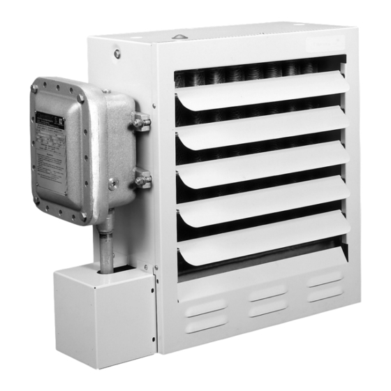
- Page 1 SALES 5200-2474-000 REFERENCE 161-302421-006 MAY, 2002 DATE INSTALLATION, OPERATION RENEWAL PARTS IDENTIFICATION X Series (Model B) Explosion Proof Heater 2” 2” Class I Group C & D, Div. 1 & 2 Class II Groups E, F & G T3B - 165°C (329°F) 11-1/16”...
- Page 2 Read Carefully - These instructions are written to help you pre- 6. Install and operate in upright position only. Refer to Figure 3 vent difficulties that might arise during installation of heaters. for level requirements. Failure to comply will cause overheat- Studying the instructions first may save you considerable time and ing of the element and shutting down the unit by tripping the money later.
-
Page 3: Installation
INSTALLATION the use of a mounting kit (ceiling, wall or pole) available from Marley. (Figures 5, 6 and 7) Fire/Explosion Hazard. Mount only in upright posi- The ceiling or wall mounting surface and the anchoring provi- sion must be sufficient to support the combined weights of the unit tion and observe nameplate mounting clearances. -
Page 4: Mounting Kits
MOUNTING KITS Wall Mount Kit Pole or Wall Mount Kit Model # XMB-12 12” Fan (3-10 kW) Model # XPM-12 12” Fan (3-10 kW) Model # XMB-16 16” Fan (15-20 kW) Model # XPM-16 16” Fan (15-20 kW) Model # XMB-20 20” Fan (25-35 kW) Model # XPM-20 20”... - Page 5 WIRING AND WIRING DIAGRAMS 4. The fan motor is factory wired at the same voltage, and phase as the heating elements. All motors are thermally protected and ELECTRIC SHOCK HAZARD. Disconnect all power connected to the main supply contactor. On three phase units, it is necessary to verify that the fan rotation is correct.
-
Page 6: Wiring Diagrams
WIRING DIAGRAMS DIAGRAM I Refer to Name Plate for Input Voltage L1 L2 Optional Transformer Color Code Tabulation Disconnect PRI. XFMR 120V SEC 24V SEC Switch VOLT. LEAD CLRS. LEAD CLRS. LEAD CLRS. Elements BLK/RED 575/600 1 PH Motor Optional Refer to Nameplate for Transformer Voltage... -
Page 7: Model Number Description
MODEL NUMBER DESCRIPTION Series Wattage Voltage Phase Control Version Suffix Explosion Proof 300=3.0kW 8=208Volt 1=1 Phase 2=24Volt T=Thermostat Heater for 500=5.0kW 4=240Volt 3=3 Phase 1*120Volt L=Pilot Light (Heater On) Hazardous 750=7.5kW 48=480Volt K=Pilot Light (Heater Tripped) Locations 1000=10.5kW 6=575Volt S=Selector Switch (Fan Only) 1500=15.0kW D=Disconnect Switch (15 Amp 3PH) 1800=18.0kW... - Page 8 MAINTENANCE AND REPAIR The occurrence of the manual reset limit control to trip is an abnor- mal condition. Care should be taken to determine the exact reason that the high limit control tripped. Possible problem areas could be dirty heat exchanger, blocked air inlet or outlet, fan/motor mal- function, too high operating ambient, incorrect operating voltage, or leaking heat exchanger.
-
Page 9: Control Transformer
MAINTENANCE AND REPAIR 3. Removal of fan blade does not require that the motor wiring be When provided, the following components are located in the cast disturbed. To clean, service or change the fan blade proceed as aluminum hazardous location enclosure. Remove cover and retain- follows: ing bolts to gain access the following items (See Figure 16): A. - Page 10 RENEWAL PARTS IDENTIFICATION Electrical Control Voltage 120V Contactor 072-304551-002 072-304551-008 Transformer 208/240/480 PRI 315-304252-002 315-304252-001 Transformer 575 PRI 315-304252-005 315-304252-003 Aux. Contactor 072-304551-102 072-304551-102 Transformer Contactor Figure 16 Figure 17...
- Page 11 RENEWAL PARTS IDENTIFICATION Motor, Element and Heat Exchanger Parts Common Parts Shown in Figure 17 1/4 HP 3, 5, Motor Heat Exchanger* 7.5 &10 15 &18 25, 30 & 35 Item# Description Model Item 19 Item 49 Part No. Part No. Part No.
- Page 12 LIMITED WARRANTY All products manufactured by Marley Electric Heating are warranted against defects in workmanship and mate- IMPLIED WARRANTIES OF MERCHANTABILITY AND FITNESS FOR A PARTICULAR PURPOSE WHICH EXCEED rials for one year from date of installation. This warranty does not apply to damage from accident, misuse, or THE AFORESAID EXPRESSED WARRANTIES ARE HEREBY DISCLAIMED AND EXCLUDED FROM THIS AGREE- alteration;...
Need help?
Do you have a question about the Marley X B Series and is the answer not in the manual?
Questions and answers