Advertisement
Quick Links
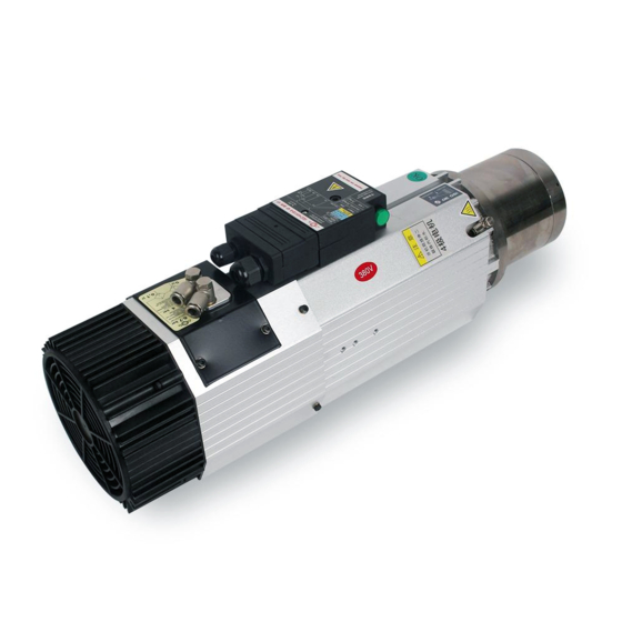
HQD Air-cooled automatic tool-change electrical spindle
Notices of installation, application and maintenance
I. About the document
Every sold automatic tool-change electrical spindle is enclosed with electronic
document of application and maintenance manual; please read the document carefully.
The document highlights the notices which shall be read carefully by personnel of
application and maintenance of HQD electrical spindle, and at the same time, the
electronic document of detailed application and maintenance manual shall be taken as
reference.
All the personnel who perform operations (installation, application and maintenance) to
HQD electrical spindle shall be considered that they have already clearly understood
the document and shall operate strictly according to the document and the electronic
documents of application and maintenance manual; otherwise, all the consequences and
loss shall be borne by users. If the document or the electronic documents are not
available, please ask the supplier to provide them.
II. Avoid hazards and dangers
1. All the operations to the electrical spindle, such as cleaning, maintenance and
service, shall be performed after power off and the complete stop of the spindle;
2. The electrical spindle shall be equipped with safety protection device, otherwise, the
components with high rotary speed would harm or hurt the people near the
components;
(GDL70-24Z/9.0)
Advertisement

Summary of Contents for HQD GDL70-24Z/9.0
- Page 1 The document highlights the notices which shall be read carefully by personnel of application and maintenance of HQD electrical spindle, and at the same time, the electronic document of detailed application and maintenance manual shall be taken as reference.
- Page 2 4. Do not wear loose or saggy clothing (such as tie and wide sleeve clothing, etc.) for operators of electrical spindle; ladies shall tie up long hair; 5. Apply specified tool holder of HQD, otherwise, it would damage the broach structure of electrical spindle, and the tool holder may be thrown out and causes personal injury;...
- Page 3 as 6~7bar (1bar=1kg), and the other set as 4bar, which will be indicated on electrical spindle. Please make sure input correct air pressure. Regarding to 6~7kg tool-change loop, please apply solenoid valve with high quality to make sure no compressed air would leak to the line of 6~7bar when the electrical spindle rotating with high speed;...
- Page 4 9) There shall be at least 10cm space behind the cooling fan of electrical spindle, so that the air could enter into fan freely (the fan blows the air into electrical spindle); 10) Regarding to the compressed air that enters into electrical spindle, please perform the pneumatic connection diagram according to page 44 in electronic documents of detailed instruction;...
-
Page 5: Correct Application
Please emphasize to read following pages: Page 19: installation dimensions (Appendix 1); Page 24: parameters of motor (Appendix 2); Page 40: installation requirements; Page 44: pneumatic connection diagram (Appendix 3) – pay special attention! Page 46: connection diagram of electrical signal lines (Appendix 2); ... - Page 6 of application. If it is necessary to replace these parts, please purchase the parts that specified or approved by supplier of electrical spindle, because all these parts shall perform dynamic balance as well. Regarding to the dynamic balance of the tool, normally each tool has its allowed rotate speed.
- Page 7 0.1~0.2mm. Make sure to apply high speed tool holder that specified by supplier of HQD electrical spindle, otherwise, it may cause the rivet dropping from the handle because of the cooperation between rivets, and the draw bar will return sharply by the effect of spring, and causes the broken of draw bar.
- Page 8 When the electrical spindle pick the tool from tool changer, it shall pay attention to make the z axle move upward after the tool holder leave the clamp horizontally, otherwise, if the tool holder moves upward in clamp, it will damage the tool changer and breaks the draw bar of electrical spindle;...
- Page 9 sticky, such as wax, which may sticky on the conical surface of tool holder and the inner taper wall of electrical spindle during machining, therefore it shall clean the surfaces at any time; otherwise, it may cause the eccentricity of tool holder, and make the electrical spindle loses dynamic balance and has sharp vibration under high speed rotating, and the bearing will be damaged quickly.
- Page 10 Appendix 1 1. Installation dimensions for short head type - GDL70-24Z/9.0 ISO30...
- Page 11 Appendix 1 2. Installation dimensions for long head type - GDL70-24Z/9.0 ISO30...
- Page 12 Appendix 2 GDL70 Wiring Diagram Pin Layout of Signal Connector Pin Layout Description of Signal Connector Description Transducer S2 | Tool Pop-up | Output | PNP NO | Transducer S1 | Tool Locked | Output | PNP NO | +24V DC power supply for S1, S2 +24V DC power supply for +24V pin of button light 0V DC power supply for S1, S2 +24V DC power supply for NO pin of button switch...
- Page 13 Appendix 3 9.4.2 Functional diagram for the connection of compressed air of electrical spindle Figure 9.6 presents the typical connection of compressed air system, and the system shall be prepared by customer. Apply two solenoid valves to decrease the risk of system failures.
- Page 14 Pressure switch A pair of three-way mono-stable solenoid valve Apply two separate loops to connect the solenoid valves (position of ref.7 in figure 9.6) to numerical control unit or manual control system. Important notice: air source of compressed air shall be dry and filtered.
- Page 15 temperature ℃ characteristic three-core thermistor -20~25℃ ≤300Ω ≤90℃ ≤750Ω 105℃ ≤1650Ω 115℃ ≤3990Ω ≥125℃ ≥12KΩ Allowed storage temperature: -25 ℃ ~ 160 ℃ , the maximum operation voltage: 25Vmax, and the maximum current: 100mAmax. Application method 1 for thermistor: connect the thermistor into the control end of frequency converter;...
- Page 16 as an example, it will output the high level when the stator temperature rise resistance is 1650 Ω (when the resistance of single core thermistor is 550 Ω ), and the motorized spindle will stop when the system detects the high voltage signal. It will output the low level when the stator temperature drop resistance is 750 Ω...
Need help?
Do you have a question about the GDL70-24Z/9.0 and is the answer not in the manual?
Questions and answers