
Summary of Contents for FAHM ULM84 Series
- Page 1 FAHM Co. Ultrasonic Level Transmitter Industrial Automation ULM84 Series User Manual Dec.2020 Doc. ULM84 Rev.99-12 Ultrasonic Level Transmitter ULM84 User Manual Page 1 of 21 www.faraboard.com...
-
Page 2: Installation
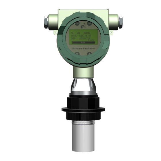
FAHM Co. Ultrasonic Level Transmitter Industrial Automation ULM84 Series User Manual Dec.2020 Doc. ULM84 Rev.99-12 1. Introduction Ultrasonic Level Transmitter ULM84 is designed to measure the level of pasty, solid particles and liquids in a tank in a non-invasive/non-contact measurement manner. -
Page 3: Transmitter Startup
FAHM Co. Ultrasonic Level Transmitter Industrial Automation ULM84 Series User Manual Dec.2020 Doc. ULM84 Rev.99-12 2- To retrieve the best wave response, the angle between the probe and the level should be right angle. 3- There should be no bubble on the liquid level. - Page 4 FAHM Co. Ultrasonic Level Transmitter Industrial Automation ULM84 Series User Manual Dec.2020 Doc. ULM84 Rev.99-12 serial number on startup and starts to search the level at the same time. Next, while still keeping the searching operation on, it displays the HART identification number (default to 00) and in case the search succeeded, calibration operation follows.
- Page 5 FAHM Co. Ultrasonic Level Transmitter Industrial Automation ULM84 Series User Manual Dec.2020 Doc. ULM84 Rev.99-12 Figure 10- Transmitter’s keyboard and display ENT Key It is used to confirm a setting or to open the settings of any menu; so if we be in setting the value of a parameter mode, the value would be saved and the setting mode would be exited.
- Page 6 FAHM Co. Ultrasonic Level Transmitter Industrial Automation ULM84 Series User Manual Dec.2020 Doc. ULM84 Rev.99-12 7. Measurement Modes The device lets the user choose which quantity to measure; i.e. the user can choose to measure Level, Distance, Volume or the Mass.
- Page 7 FAHM Co. Ultrasonic Level Transmitter Industrial Automation ULM84 Series User Manual Dec.2020 Doc. ULM84 Rev.99-12 As displayed below, a display of Custom variable/ Temperature is possible. R0010 77.14% Temp: 18.12 °C 16.342 mA 77.14% Figure 14- Custom Value/Temperature display mode The definition of Custom variable (CV) is only possible through HART protocol connection to the device and there is no way to define them using the keys on the device.
- Page 8 FAHM Co. Ultrasonic Level Transmitter Industrial Automation ULM84 Series User Manual Dec.2020 Doc. ULM84 Rev.99-12 Table 3- description of displayed statements above the screen Description Symbol Parameter The Speed is normal (near 1 meters per The Speed is high (near 8 meters per...
-
Page 9: Settings Menu
FAHM Co. Ultrasonic Level Transmitter Industrial Automation ULM84 Series User Manual Dec.2020 Doc. ULM84 Rev.99-12 9. Settings Menu ----Display Setting---- LCD Brightness >> ESC/ ENT Level: 8.313 m Distance: 1.687 m Password Password Password ... - Page 10 FAHM Co. Ultrasonic Level Transmitter Industrial Automation ULM84 Series User Manual Dec.2020 Doc. ULM84 Rev.99-12 Table 4- ULM84 settings in a glance Parameter’s No & Name Description Settings Type Choose Measurement Variable between Level, Distance, Volume and P01 (Device Mode)
- Page 11 FAHM Co. Ultrasonic Level Transmitter Industrial Automation ULM84 Series User Manual Dec.2020 Doc. ULM84 Rev.99-12 10. Basic Menu (Password: 01000) In the previous section, a list of basic and advanced transmitter settings was seen; in this section, the basic settings will be explained in more detail and with details about each of the menus.
- Page 12 FAHM Co. Ultrasonic Level Transmitter Industrial Automation ULM84 Series User Manual Dec.2020 Doc. ULM84 Rev.99-12 Define Distance between Transmitter’s Probe to the Reference Point ( P04 Probe Height In order to calibrate the equipment, in addition to the reference level (with which other surfaces are measured), the end level of the probe and the maximum and minimum levels must be determined.
- Page 13 FAHM Co. Ultrasonic Level Transmitter Industrial Automation ULM84 Series User Manual Dec.2020 Doc. ULM84 Rev.99-12 For example, in Figure 19 there is an obstacle whose distance to the bottom of the transmitter probe is L₁; therefore, the "P06 Dead Band" parameter must be set to L₁ or slightly more; thus, the equipment will ignore the above obstacle.
- Page 14 FAHM Co. Ultrasonic Level Transmitter Industrial Automation ULM84 Series User Manual Dec.2020 Doc. ULM84 Rev.99-12 Define Level Lookup Table Values ( P15 Length/ Volume Table This menu is activated if in menu #12 the method of volume calculation by level based on a lookup table is selected.
- Page 15 FAHM Co. Ultrasonic Level Transmitter Industrial Automation ULM84 Series User Manual Dec.2020 Doc. ULM84 Rev.99-12 Figure 21- Device Terminal, as seen as the back cover is opened Define Liquid Level to Activate Low-Low Alarm ( P23 Alarm Limit LO-LO The user can set a value commensurate with the level at which he expects this alarm to work;...
- Page 16 FAHM Co. Ultrasonic Level Transmitter Industrial Automation ULM84 Series User Manual Dec.2020 Doc. ULM84 Rev.99-12 The errors in Figure 22 due to the following factors may be shown on the display. In the event of these errors, in addition to the displays shown in Figure 22, the alarm will be announced by the transmitter according to the user's selection based on the table above.
- Page 17 FAHM Co. Ultrasonic Level Transmitter Industrial Automation ULM84 Series User Manual Dec.2020 Doc. ULM84 Rev.99-12 Define equivalent level value of 4 mA current output according to the reference level( P49 4 mA Setup After defining the reference point, adjust this parameter to specify the minimum liquid level in a way that transmitter would output 4mA current when this level is detected.
- Page 18 FAHM Co. Ultrasonic Level Transmitter Industrial Automation ULM84 Series User Manual Dec.2020 Doc. ULM84 Rev.99-12 2- The minimum level value that the user expects, if the liquid is at that level, to have a 4 mA output current transmitter, is determined relative to the reference level and its value is entered in the "P49 4mA Setup"...
- Page 19 FAHM Co. Ultrasonic Level Transmitter Industrial Automation ULM84 Series User Manual Dec.2020 Doc. ULM84 Rev.99-12 If the above is done correctly, the amount of liquid level according to the figure is 7 meters above the reference level and the read number of the equipment up to the liquid level will be 2 meters; therefore, the number +9 must be considered for the probe level of the transmitter.
- Page 20 FAHM Co. Ultrasonic Level Transmitter Industrial Automation ULM84 Series User Manual Dec.2020 Doc. ULM84 Rev.99-12 So for the second sample tank, level parameters should be set as follows. Table 9- Setting parameters of second sample tank Parameter No. (Name) Value...
- Page 21 FAHM Co. Ultrasonic Level Transmitter Industrial Automation ULM84 Series User Manual Dec.2020 Doc. ULM84 Rev.99-12 “No Echo” screen (Refer to Figures 9 or 22) Liquid is over range Wrong / unreasonable Deadband setting (refer to P06 Dead band) Power supply mismatch...
Need help?
Do you have a question about the ULM84 Series and is the answer not in the manual?
Questions and answers