Table of Contents
Advertisement
Quick Links
Advertisement
Table of Contents

Related Manuals for PB International UFKS

Summary of Contents for PB International UFKS
- Page 1 Installation and operating instructions UFKS and AquaproteQ Ultrafiltration gatekeeper system Suitable for UFKS and AquaproteQ with touchscreen IMPORTANT READ CAREFULLY BEFORE USE KEEP FOR FUTURE REFERENCE ENGLISH PB International BV Stikkenweg 50 7021 BN, Zelhem The Netherlands 1 of 29...
-
Page 2: Abbreviations And Terms
BMS: Building management system ▪ UF: Ultrafiltration ▪ Device: Delos UFKS Ultrafiltration system with peripheral equipment ▪ User: Person who uses water from the downstream installation, or otherwise comes into contact with the device (with the exception of the installer or service engineer). -
Page 3: Version Number
1.7. Liability of the installer The installer is responsible for the installation of the device and the initial commissioning of the device. The installer must observe the following instructions: ▪ Read these installation and operating instructions carefully before you install the product. - Page 4 1.11. Safety If leakage occurs outside the equipment: ▪ Disconnect the electrical voltage of the equipment. ▪ Turn off the water supply. ▪ Have a competent installer repair the leak. ▪ If the leak is in front of the water meter, notify the water supplier If leakage occurs inside the equipment: ▪...
-
Page 5: General Guidelines
When using a pressure booster system, it must be placed in the supply to the ultrafiltration equipment. Modifications to the equipment may only be carried out after explicit written permission from PB International BV. ▪ The device may only be used as described in section 4.1. -
Page 6: Application Conditions
The maximum ambient temperature is 40 °C / 104 °F. 4. Technical description 4.1. General description The device bears the product name 'UFKS'. This is a gatekeeper system based on ultrafiltration, intended to keep the downstream drinking water installation legionella safe. 6 of 29... - Page 7 The product is designed for use in the main feeder of a complete indoor drinking water installation (gatekeeper concept), or a part thereof, with a standard consumption capacity of up to 20 m³/h/88 GPM. The purpose of the equipment is to provide the downstream drinking water network with bacteria-free supply water.
-
Page 8: Operating Principle
correct operation of the filter modules. If a diaphragm failure occurs, the defective filter is automatically put out of operation. The malfunction signal then becomes active. Malfunction signal If a fault occurs because the integrity of a filter module cannot be guaranteed, a pulsating auditory signal will be heard of 85 dB. -
Page 9: Main Components
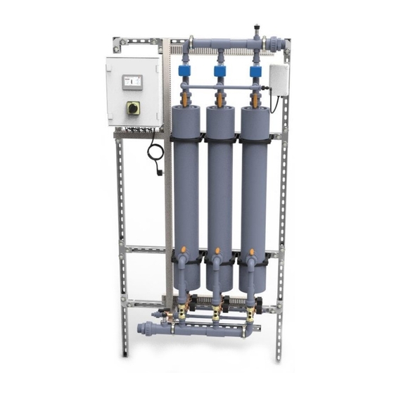
Displays the filter The indicated filter is number of flushed backwards. potentially defective filter. 4.5. Main components 1. Control box 11. Mounting bracket filter modules 2. Inlet pressure sensor 12. Metal frame 3. Supply water connection 13. Filter module 4. Information touchscreen panel 14. -
Page 10: Technical Data
4.7. Technical data AquaproteQ UFKS 2-160- 2-160- 3-160- 4-160- 4-160- Product type 1000 1000 Item number 10042 10043 10044 10046 10047 10048 10049 10050 Supply connection 1” BSP O.T. 1 ½” BSP O.T. Permeate connection 1” BSP O.T. 1 ½” BSP O.T. -
Page 11: Installation Instructions
5. Installation instructions Installation work must be carried out by a qualified installer in accordance with local and national regulations. 5.1. Scope of delivery The delivery includes: UFKS ▪ Ultrafiltration installation on metal frame, including; ▪ Mounted Control box ▪... -
Page 12: Installation
▪ Fewer used tapping points, and therefore pipes that flow through little, must be secured by installing a valve / inlet combination with a controllable check valve at the beginning of this pipe, directly on a well-flowing pipe. ▪ An EA type check valve must be installed in front of the device. 5.3. - Page 13 5.5. Mounting Mounting of the UFKS After determining the location, connect the device according to the instructions below. Remove the device from the outer packaging. Check the packaging and the product for damage. Never install a damaged product. Clear the wall where the system will be installed. Check if the wall can carry the weight of the system.
- Page 14 [2]. coupling marked with [1]. Mounting of the UFKS After determining the location, connect the device according to the instructions below. Remove the device from the outer packaging. Check the packaging and the product for damage.
- Page 15 Connecting the UFKS Connect the cold water drinking water Then connect the downstream drinking water supply for the filter to the threaded system to the threaded coupling marked with [2]. coupling marked with [1]. Wrong connection results in a non-working system.
- Page 16 Connect the drainage pipes, indicated in figures [3] and [4], to the drainage to the drain by means of the threaded couplings separately. An individual visible free outlet must be installed in the discharge pipes of the device according to the illustration and table below.
- Page 17 Electrical connection Open the control box with the appropriate key. Insert the end of the supplied power cord Loosen the empty swivel. through the cable gland. Connect the power Take the power cord and keep it away from the cord. Turn the swivel hand-tight and close the wall socket.
-
Page 18: Putting The Equipment Into Operation
6. Putting the equipment into operation After the installation of the equipment it is important to carry out the following steps: 6.1. Check points ▪ Check that the voltage indicated on the equipment corresponds to the local mains voltage before you connect the equipment. ▪... -
Page 19: Factory Settings
Insert the plug into the grounded wall socket. Wait until the device has booted and press START. The device will start flushing the present filters immediately. The PB Filter elements contain Glycerine and Sodium sulfite for preservation. Before first use, the device must therefore be flushed for at least 10 minutes to remove these substances from the filter! Open the nearest tap of the downstream installation to flush the system for at least 10 minutes. -
Page 20: Menu Layout
Menu layout The menu layout can be found in the overview below. Start manual integrity test Change display settings Alarmhistory cycle Settings Set date and time. Set times for integrittest en flushing. Set date and time. Set times for integrity test and flushing. Turn [SET TIMES] on and off the flush and integrity test. - Page 21 Manual sub-cycle per filter. [MANUAL] Integritytest Forward Flush Backward flush 7. Alarms and malfunctions 7.1. Signaling The following table shows the possible malfunctions with the possible causes and the corresponding action. In the event of any malfunctions, we strongly advise you to contact your supplier by telephone before taking any action.
- Page 22 ▪ Have the system checked and There is a little water ▪ There is a risk of a leak repaired by an authorized service under the device technician. ▪ Close the main tap of the drinking There is a large amount water.
- Page 23 ▪ ERROR 212 ▪ The integrity test ▪ Contact your supplier for support. procedure has been postponed 72 times. ▪ ERROR 213 ▪ (Semi-)annual service ▪ Contact your supplier for support. recommended. 7.2. Actions in the event of malfunction In the event of a malfunction, never remove the plug from the wall socket without consultation.
-
Page 24: Maintenance And Warranty
7.3. Actions in the event of a power failure Power failure does not adversely affect the operation of the product. There will still be safe water in the pipeline. However, both the flushing and integrity test function no longer work. It is important that the voltage problem is solved as quickly as possible in order to guarantee the integrity and correct functioning of the filters. -
Page 25: Maintenance Log
defective Services. In performance of its obligations hereunder, Seller will not control the actual operation of either Buyer’s systems or the Equipment at the Buyer’s site. Warranty repair, replacement or re-performance by Seller shall not extend or renew the applicable warranty period. The warranties and remedies are conditioned upon (a) proper unloading, handling, storage, installation, use, operation, and maintenance of the Equipment and Buyer’s facility and all related system in accordance with Seller’s instructions and, in the absence,... -
Page 26: Spare Parts List
8.3. Spare parts list Part Amount in product Art. Nr. 1” NO solenoid valve 4 pcs. per filter 31076 ½” NC solenoid valve 1 + 5 pcs. per filter 30062 Air sensor 3 pc. 30366 Air pump 1 pc. 30007 Check valve 32mm thread 1 pc. - Page 27 8.6. Maintenance table Date Observation / Maintenance work Action Date Initials 27 of 29...