
Subscribe to Our Youtube Channel
Summary of Contents for SECURITY SENSOR BARRIER-24.M500
- Page 1 SECURITY SENSOR BARRIER-24.M500 BARRIER-24.M300 BARRIER-24.M200 BARRIER-24.M100 BARRIER-24.M50 User Manual EU-type examination CERTIFICATE (Radio Equipment Directive 2014/EU, Annex III) No. 0120-CC-V0008-20 2020...
-
Page 2: Table Of Contents
BARRIER-24.M500, BARRIER-24.M300, BARRIER-24.M200, BARRIER-24.M100, BARRIER-24.M50 www.SECURITY-SNESORcom Contents Introduction ..........................3 Description and Operation of the Sensor ..............4 Purpose of the Sensor ....................4 Technical Specifications ..................5 Contents of the Device .................... 9 Structure and Operation ..................11 Measuring Devices, Instruments and Accessories ..........16 Making ........................ -
Page 3: Introduction
24.M (general purpose) (referred to as the sensors for all the modifications) produced in five modifications: BARRIER-24.M50, BARRIER-24.M100, BARRIER-24.M200, BARRIER-24.M300, BARRIER-24.M500 differing in dimensions and maximum range of operation. The User Manual contains information necessary for learning the sensors and their operation principle, mounting, powering the sensors and their correct exploitation. -
Page 4: Description And Operation Of The Sensor
BARRIER-24.M500, BARRIER-24.M300, BARRIER-24.M200, BARRIER-24.M100, BARRIER-24.M50 www.SECURITY-SNESORcom Description and Operation of the ensor Purpose of the Sensor 1.1.1 The Protection Linear Microwave Bistatic sensors BARRIER-24.M (general purpose) are intended for the protection of flat open sites, for generation and transmission of the alarm signal to the control panel in case of intruder crossing the protected site. -
Page 5: Technical Specifications
«bent» is less than 0,98, because a man can pass lower the detection zone. ** For the sensors BARRIER-24.M300, BARRIER-24.M500: the probability of intruder detection by the sensors is equal on all the range of the detection zone and is 0,98, however the height of the detection zone close to the sensors Tx and Rx units is reduced. - Page 6 BARRIER-24.M500, BARRIER-24.M300, BARRIER-24.M200, BARRIER-24.M100, BARRIER-24.M50 www.SECURITY-SNESORcom Table 1.2 – Height of the sensors detection zone Names of sensors Height of the detection zone (h), m, not less than BARRIER-24.M50 1,3* BARRIER-24.M100 1,5* BARRIER-24.M200 1,6* BARRIER-24.M300 1,8* BARRIER-24.M500 1,8* ____________________ * In the middle of the sector at the maximum range 1.2.2...
- Page 7 BARRIER-24.M500, BARRIER-24.M300, BARRIER-24.M200, BARRIER-24.M100, BARRIER-24.M50 www.SECURITY-SENSOR.com 1.2.3 The shape of the detection zone generated by the sensors BARRIER-24.M50, BARRIER-24.M100, BARRIER-24.M200 installed on the fence, maximum operational range of the sensors, maximum width of the sensors detection zone, maximum height of the sensors detection zone are given in Figure 1.3 and Table 1.4.
- Page 8 1.2.25 Full mean lifetime – not less than 8 years. 1.2.26 1.2.27 Weight of the sensors including fixing elements, up to: – 2,9 kg for the sensors BARRIER-24.M300, BARRIER-24.M500; – 1,4 kg for the sensors BARRIER-24.M200, BARRIER-24.M100, BARRIER- 24.M50. 14.01.2021...
-
Page 9: Contents Of The Device
BARRIER-24.M500, BARRIER-24.M300, BARRIER-24.M200, BARRIER-24.M100, BARRIER-24.M50 www.SECURITY-SENSOR.com Contents of the Device 1.3.1 There are several modifications of the sensors depending on the maximum operation range (see Table 1.5). Table 1.5 – Modifications of the Protection Linear Microwave Bistatic sensors BARRIER-24.M (general purpose) Name Security sensor BARRIER-24.M50... - Page 10 BARRIER-24.M500, BARRIER-24.M300, BARRIER-24.M200, BARRIER-24.M100, BARRIER-24.M50 www.SECURITY-SNESORcom Continuation of Table 1.6 Protection Linear Microwave Bistatic sensor BARRIER-24.M100 Transmitter unit Receiver unit Mounting kit see Table 1.7 Kit of instruments and see Table 1.8 accessories User Manual Passport Package Protection Linear Microwave Bistatic sensor BARRIER-24.M200...
-
Page 11: Structure And Operation
BARRIER-24.M500, BARRIER-24.M300, BARRIER-24.M200, BARRIER-24.M100, BARRIER-24.M50 www.SECURITY-SENSOR.com 1.3.3 The contents of the mounting kit is given in Table 1.7. Table 1.7 – The contents of the MK Name Q-ty Note 1 Mounting kit containing of: 1.1 Input of the corrugated hose 1.2 Corrugated tube РА601013F0... - Page 12 BARRIER-24.M500, BARRIER-24.M300, BARRIER-24.M200, BARRIER-24.M100, BARRIER-24.M50 www.SECURITY-SNESORcom 1.4.2.1 The Tx unit (overall dimensions 195,5х154,5х100 mm) (see Figure 1.4) contains a plastic housing with a microwave module and a modulator with configuration elements. The housing contains a parabolic insertion. The housing is closed with a cover.
- Page 13 Note corrugated tube may differ depending on the shipment conditions 1.4.3 Structure of the sensors BARRIER-24.M300, BARRIER-24.M500 1.4.3.1 The Tx unit (overall dimensions 395х182х100 mm) (see Figure 1.5) contains two connected with each other plastic housings, with microwave modules and parabolic insertions inside.
- Page 14 BARRIER-24.M500, BARRIER-24.M300, BARRIER-24.M200, BARRIER-24.M100, BARRIER-24.M50 www.SECURITY-SNESORcom sight bar to make it easy to adjust the sensor. The configuration elements are covered with a cap. The cap is protected against unauthorized opening with a button. The unit contains a bracket for pole mounting. Use the 8-core cable brought out from the unit through the input of the corrugated hose to connect the Rx unit to the junction box or power supply unit.
- Page 15 BARRIER-24.M500, BARRIER-24.M300, BARRIER-24.M200, BARRIER-24.M100, BARRIER-24.M50 www.SECURITY-SENSOR.com 1.4.4 Configuration elements of the sensors BARRIER-24.M (general purpose) 1.4.4.1 The location of the configuration elements under the cap of the Tx unit (Rx unit) are given in Figures 1.6, 1,7. 1 – socket «TEST»;...
-
Page 16: Measuring Devices, Instruments And Accessories
BARRIER-24.M500, BARRIER-24.M300, BARRIER-24.M200, BARRIER-24.M100, BARRIER-24.M50 www.SECURITY-SNESORcom 1.4.5.3 The reception and indication of alarm signals is made by security systems (panels) controlling the relay contacts. In case of alarm the normally closed relay contacts are broken. 1.4.5.4 The alarm information is duplicated via the interface RS-485. -
Page 17: Making
BARRIER-24.M500, BARRIER-24.M300, BARRIER-24.M200, BARRIER-24.M100, BARRIER-24.M50 www.SECURITY-SENSOR.com Marking 1.6.1 The sensors marking contains: – trademark of the factory manufacturer; – name of the sensor unit; – factory serial number; – year and quarter of manufacture. 1.6.2 The transport and consumer package marking contains: –... -
Page 18: Preparation For Use
BARRIER-24.M500, BARRIER-24.M300, BARRIER-24.M200, BARRIER-24.M100, BARRIER-24.M50 www.SECURITY-SNESORcom 2.1.7 On sites with extra storm danger it is necessary to use external lightning guard units (LGU). It is recommended to use lightning guard units in case the connection lines is more than 300 m. - Page 19 BARRIER-24.M500, BARRIER-24.M300, BARRIER-24.M200, BARRIER-24.M100, BARRIER-24.M50 www.SECURITY-SENSOR.com 2.3.1.4 Do electrical fitting of the sensors, connection to junction boxes and power supply unit according to the security system project. 2.3.2 Installation procedure of the sensors BARRIER-24.M (general purpose). 2.3.2.1 Meet the requirements of P. 2.1.2.
- Page 20 2.3.2.2.2 For continuous long protection boundary with the sensors BARRIER-24.M300, BARRIER-24.M500 it is allowed to install two Tx units (Rx units) on one pole without overlapping the detection zones of adjacent sectors (see Figure 2.2). Figure 2.2 – Installation of Rx units (Tx units) of the sensors BARRIER-24.M300, BARRIER-24.M500 on one pole without overlapping the adjacent detection zones...
- Page 21 BARRIER-24.M500, BARRIER-24.M300, BARRIER-24.M200, BARRIER-24.M100, BARRIER-24.M50 www.SECURITY-SENSOR.com regions with much snow assure the height of the pole not less than 1500 mm above the ground. 2.3.2.4 It is possible to install the poles SUPPORT-2 and SUPPORT-2,5 with concreting. The poles are made of metal tube 76 mm in diameter and differ in length (2 m and 2,5 m accordingly).
- Page 22 BARRIER-24.M500, BARRIER-24.M300, BARRIER-24.M200, BARRIER-24.M100, BARRIER-24.M50 www.SECURITY-SNESORcom 1 - SUPPORT-2 or SUPPORT-2,5; 2 - plastic cap; 3 - holes for inserting the sensor cable inside the pole; 4 - holes for inserting the mains cable and sensor cable; 5 - holes for inserting the mains cable;...
- Page 23 BARRIER-24.M500, BARRIER-24.M300, BARRIER-24.M200, BARRIER-24.M100, BARRIER-24.M50 www.SECURITY-SENSOR.com 2.3.2.6 Lay the mains cables according to the security system project. It is recommended to use cables with screen or metal cover. Choose the cables cross-section to assure the supply voltage not less than 9 V on every sensor unit.
- Page 24 BARRIER-24.M500, BARRIER-24.M300, BARRIER-24.M200, BARRIER-24.M100, BARRIER-24.M50 www.SECURITY-SNESORcom 1 – pole; 5 – input of the corrugated hose – 1 pc. 2 – bracket; 6 – corrugated tube – 1 pc.; 3 – Tx unit (Rx unit); 7 – screw (from the Bracket kit);...
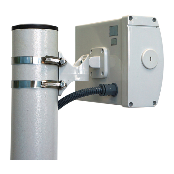
- Page 25 BARRIER-24.M500, BARRIER-24.M300, BARRIER-24.M200, BARRIER-24.M100, BARRIER-24.M50 www.SECURITY-SENSOR.com 2.3.4 Mounting of the sensors BARRIER-24.M300, BARRIER-24.M500 on a pole 2.3.4.1 Use two buckles pos. 3 (from the MK) to install the bracket pos.4 (from the MK) on the pole pos.2, as shown in Figure 2.5. Fix the bracket on the pole. It is allowed to remove long free ends of buckles.
- Page 26 BARRIER-24.M500, BARRIER-24.M300, BARRIER-24.M200, BARRIER-24.M100, BARRIER-24.M50 www.SECURITY-SNESORcom 2.3.5 Installation of the sensors BARRIER-24.M (general purpose) on BRACKET-1000, BRACKET-1250. 2.3.5.1 If it is impossible to install the poles and there is a rigid fence, we recommend using BRACKET-1000, BRACKET-1250 to mount the sensors BARRIER-24.М (general purpose).
- Page 27 BARRIER-24.M500, BARRIER-24.M300, BARRIER-24.M200, BARRIER-24.M100, BARRIER-24.M50 www.SECURITY-SENSOR.com Use BRACKET-120M with the carry-over 120 mm from the fence to the sensor center if the direction of beaming of the unit is perpendicular to the bearing surface or within the angle limits (90 ± 40).
- Page 28 BARRIER-24.M500, BARRIER-24.M300, BARRIER-24.M200, BARRIER-24.M100, BARRIER-24.M50 www.SECURITY-SNESORcom 2.3.6.3 Mounting procedure of the sensors on BRACKET-120M (Figure 2.8). 2.3.6.3.1 Install BRACKET-120M on the protected surface according to its exploitation documentation. 2.3.6.3.2 Use the spanner from the KIA to dismantle the component for pole fixing unscrewing the screw pos.3 from the Rx unit (Tx unit) bracket.
- Page 29 BARRIER-24.M500, BARRIER-24.M300, BARRIER-24.M200, BARRIER-24.M100, BARRIER-24.M50 www.SECURITY-SENSOR.com 2.3.6.4 The examples of installation of the sensors using the outboard brackets BRACKET-500M, BRACKET-350M, BRACKET-120M are given in Figure 2.9. 2.3.6.5 Angles of turn of the Tx unit (Rx unit) on the outboard brackets: in horizontal plane –...
- Page 30 BARRIER-24.M500, BARRIER-24.M300, BARRIER-24.M200, BARRIER-24.M100, BARRIER-24.M50 www.SECURITY-SNESORcom 2.3.7 Connection of the Sensor 2.3.7.1 Make the necessary connections of power supply circuits, signal circuits, remote control circuits according to the project diagram for the security alarm system. Rx unit and Tx unit are connected with their own cables, the conductor purpose is specified by its colour.
- Page 31 BARRIER-24.M500, BARRIER-24.M300, BARRIER-24.M200, BARRIER-24.M100, BARRIER-24.M50 www.SECURITY-SENSOR.com 2.3.7.4 The diagram of connection the sensor using the junction box JBS-15 is given in Figure 2.10. The contacts of the TAMPER button are connected sequentially with the executive relay contacts. An additional button for applying the remote control signal to the sensor is to be installed in the guard room.
- Page 32 (see Figure 2.4) of the Tx unit and Rx unit of the sensors BARRIER-24.M50, BARRIER-24.M100, BARRIER-24.M200; – loose the buckles pos.3 and the bolt pos.6 (see Figure 2.5) of the Tx unit and Rx unit of the sensors BARRIER-24.M300, BARRIER-24.M500; 14.01.2021...
- Page 33 BARRIER-24.M500, BARRIER-24.M300, BARRIER-24.M200, BARRIER-24.M100, BARRIER-24.M50 www.SECURITY-SENSOR.com – turn Tx unit and Rx unit in vertical and horizontal planes to direct them one to another using the sight bar. 2.3.8.6 Exact adjustment of the sensors using the laptop on Windows platform 2.3.8.6.1...
- Page 34 BARRIER-24.M500, BARRIER-24.M300, BARRIER-24.M200, BARRIER-24.M100, BARRIER-24.M50 www.SECURITY-SNESORcom distances from the Tx unit and Rx unit. It is recommended to begin crossing the protected sector in the middle of the protected sector. After every crossing leave the detection zone on 1-2 m and make pause from 5 to 7 s, otherwise the results of the previous crossing may influence the next one.
- Page 35 BARRIER-24.M500, BARRIER-24.M300, BARRIER-24.M200, BARRIER-24.M100, BARRIER-24.M50 www.SECURITY-SENSOR.com Disconnect the cable USB A-B from the socket «TEST» of the Rx unit. 2.3.8.10 2.3.8.10.1 Replace the cap of configuration units of the Rx unit turning it clockwise up to the stop using a screwdriver for screws with straight slot with wide blade.
- Page 36 BARRIER-24.M500, BARRIER-24.M300, BARRIER-24.M200, BARRIER-24.M100, BARRIER-24.M50 www.SECURITY-SNESORcom lightning guard unit β is recommended for use in case the segment of the interface line from the sensor to the next device is more than 500 m. In case of shorter lengths of the communication line the elements integrated into the sensor serve as the lightning guard.
- Page 37 BARRIER-24.M500, BARRIER-24.M300, BARRIER-24.M200, BARRIER-24.M100, BARRIER-24.M50 www.SECURITY-SENSOR.com 2.3.9 Operation of the sensors BARRIER-24.M50, BARRIER-24.M100, BARRIER- 24.M200 with reflectors REFLECTOR-360 (REFLECTOR-820) 2.3.9.1 In order to make the breaking of the sensor detection zone on difficult perimeter sites use REFLECTOR-360 or REFLECTOR-820. 2.3.9.2 When the sensor is used with REFLECTOR-360 (see Figure 2.14) the total...
-
Page 38: Technical Service
BARRIER-24.M500, BARRIER-24.M300, BARRIER-24.M200, BARRIER-24.M100, BARRIER-24.M50 www.SECURITY-SNESORcom 2.3.9.3 The procedure of installation and configuration of the sensors using the reflectors REFLECTOR-360 (REFLECTOR-820) 2.3.9.3.1 Mount the Tx unit, Rx unit and the reflector according to pp. 2.3.1-2.3.3 of the present User Manual and Figure 2.14. Mount the Tx unit, Rx unit and the reflector on the same height respectively to the ground. - Page 39 BARRIER-24.M500, BARRIER-24.M300, BARRIER-24.M200, BARRIER-24.M100, BARRIER-24.M50 www.SECURITY-SENSOR.com Table 3.1 – Schedule and periodicity of technical service Periodicity Technical service works month Checking of the sensors operability Checking of the sensors appearance Checking of the protected sector state 3.3.2 Checking of the sensors operability In order to check remotely the sensors operability, apply the voltage of 5 …...
-
Page 40: Troubleshooting Guide
BARRIER-24.M500, BARRIER-24.M300, BARRIER-24.M200, BARRIER-24.M100, BARRIER-24.M50 www.SECURITY-SNESORcom Troubleshooting Guide The list of possible failures is given in Table 4.1. Table 4.1 – The list of possible failures Failure, Possible reason Repair External manifestation 1 Constant alarm 1 Communication line is Check the cable integrity and on the control and damaged. -
Page 41: Storage
BARRIER-24.M500, BARRIER-24.M300, BARRIER-24.M200, BARRIER-24.M100, BARRIER-24.M50 www.SECURITY-SENSOR.com Storage Store the sensors in factory package on racks in the warehouse. Use heated warehouse with the temperature inside from plus 5 C to plus 40 humidity up to 80%. No vapour of acid, alkaline and other chemically active substances causing the corrosion are allowed in the warehouse. -
Page 42: The List Of Registration Of Changes
BARRIER-24.M500, BARRIER-24.M300, BARRIER-24.M200, BARRIER-24.M100, BARRIER-24.M50 www.SECURITY-SNESORcom The list of registration of changes Total Incoming Sheets (pages) numbers number of number of the sheets Document Change accompanying Signature Date (pages) in number document and changed replaced new canceled date documents 14.01.2021... - Page 43 BARRIER-24.M500, BARRIER-24.M300, BARRIER-24.M200, BARRIER-24.M100, BARRIER-24.M50 www.SECURITY-SENSOR.com 14.01.2021...
Need help?
Do you have a question about the BARRIER-24.M500 and is the answer not in the manual?
Questions and answers