
Summary of Contents for UHVD MD40
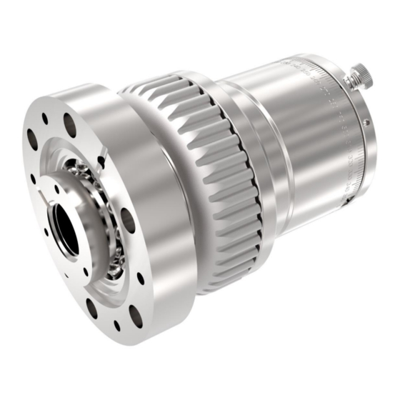
- Page 1 PRODUCT INSTRUCTION MANUAL Product Range: MD40 Product Description CF40 (2.75” OD) magnetically-coupled rotary drive (rotary feedthrough). MD40 Revision: 1.1 Author: N.Carapiet...
-
Page 2: Table Of Contents
2.1.3 Bakeout procedure......................8 Installation instructions – Dual Shaft Option ............... 9 2.1.4 2.1.5 Bakeout procedure......................11 SIDE MOUNTED STEPPER OR DC MOTORISED MD40 ........... 12 2.2.1 Description ........................12 2.2.2 Stepper Motor Details ....................... 13 2.2.3 DC Motor Details ....................... 13 Installation instructions ...................... - Page 3 MD40 PRODUCT INSTRUCTION MANUAL 3.3.3 Pneumatic Sensor Specification ..................45 Base Drive ..........................46 Dual Shaft ..........................47 Pneumatic Drive ........................48 Side Mounted Stepper Motor Options ................... 49 Side Mounted DC Motor Options ..................50 Inline Mounted Stepper Motor Options .................. 51 Inline Mounted DC Motor Options ..................
- Page 4 This equipment should be put into service only by Competent Persons who have first studied this manual and followed carefully the recommended procedures. INSTALLATION & OPERATION This manual covers installation and operation for standard MD40 configurations: Manual Actuation • Example Part Numbers:...
-
Page 5: Manually Actuated Md40
MD40 PRODUCT INSTRUCTION MANUAL MANUALLY ACTUATED MD40 2.1.1 Description Standard Drive Thimble | Manual operation. See pages 5-7. Dual Shaft Option | Rear shaft to allow the thimble to be driven directly. See pages 8-10. See the Drawing section of this manual for dimensional details. -
Page 6: Installation Instructions - Standard Drive Thimble
MD40 PRODUCT INSTRUCTION MANUAL 2.1.2 Installation instructions – Standard Drive Thimble STAGE 1 | To install the drive onto the vacuum system, the drive thimble will have to be removed in order to gain access to the flange mounting holes. - Page 7 MD40 PRODUCT INSTRUCTION MANUAL STAGE 2 | Mounting the drive CF40 Chamber Port Flange Assembly CONFLAT Gasket Mounting Bolts How to install the Flange Assembly: 1. Use an appropriate CONFLAT Gasket 2. Use 6 appropriate length Mounting Bolts and washers...
-
Page 8: Bakeout Procedure
MD40 PRODUCT INSTRUCTION MANUAL 1. Insert MD40 flange assembly 2. Insert bolts and tighten Note: when tightening bolts, care must be taken not to tighten them unevenly as this may cause the gasket not to seal properly. STAGE 3 | Replace thimble and associated parts. -
Page 9: Installation Instructions - Dual Shaft Option
MD40 PRODUCT INSTRUCTION MANUAL 2.1.4 Installation instructions – Dual Shaft Option STAGE 1 | To install the drive onto the vacuum system, the drive thimble will have to be removed in order to gain access to the flange bolt holes. - Page 10 MD40 PRODUCT INSTRUCTION MANUAL STAGE 2 | Mounting the drive CF40 Chamber Port Flange Assembly CONFLAT Gasket Mounting Bolts How to install the Flange Assembly: 1. Use an appropriate CONFLAT Gasket 2. Use 6 appropriate length Mounting Bolts and washers...
-
Page 11: Bakeout Procedure
MD40 PRODUCT INSTRUCTION MANUAL 1. Insert MD40 flange assembly 2. Insert bolts and tighten. Note: when tightening bolts, care must be taken not to tighten them unevenly as this may cause the gasket not to seal properly. STAGE 3 | Replace thimble and associated parts. -
Page 12: Side Mounted Stepper Or Dc Motorised Md40
SIDE MOUNTED STEPPER OR DC MOTORISED MD40 2.2.1 Description The stepper motor option allows for precise position control of the MD40. This can be selected with optional home sensor or home sensor with limit switches. All options are available with optional encoder and are plug and play compatible with UHV Design supplied stepper motor controller (purchased separately). -
Page 13: Stepper Motor Details
MD40 PRODUCT INSTRUCTION MANUAL 2.2.2 Stepper Motor Details See Technical Reference section for more details. Motor Specification 23 frame 4 wires 2.8A per phase (gear option 1) 17 frame, 4 wires 1.8A per phase (gear option 2-4). See Technical Reference section. -
Page 14: Installation Instructions
MD40 PRODUCT INSTRUCTION MANUAL Installation instructions STAGE 1 | The motor assembly and drive thimble will need to be removed in order to gain access to the flange bolt holes. Motor Mount Plate M5 Screw Belt Cover Retaining M3 Screws x 2... - Page 15 MD40 PRODUCT INSTRUCTION MANUAL Note: If any switch options are selected care must be taken when removing and re-fitting the motor. Make sure the thimble is rotated away from the central position. Otherwise the sensor flag will interfere with the home sensor and prevent the motor from being removed or re-fitted and may damage the switches.
- Page 16 (note: only hex head bolts can be used) 3. Place CONFLAT Gasket into flange counter bore 4. Insert MD40 flange assembly 5. Insert bolts and tighten. Note: when tightening bolts, care must be taken not to tighten them unevenly as this may cause the gasket not to seal properly.
- Page 17 MD40 PRODUCT INSTRUCTION MANUAL Refitting the Drive Thimble 1. Replace Motor Flange Clamp and tighten 6 x M4 Motor Flange Clamp Screws. 2. Push Drive Thimble over the Flange Assembly (take care when re-coupling the magnets – the magnetic coupling may cause a sudden movement) 3.
- Page 18 MD40 PRODUCT INSTRUCTION MANUAL Refitting the Motor Assembly 1. Fit Belt around the Timing Pulley. 2. Tilt motor assembly to engage Pulley with the Belt. 3. Insert and tighten Motor Mount Plate M5 Screw (the belt should be under tension).
-
Page 19: Bakeout Procedure
MD40 PRODUCT INSTRUCTION MANUAL 2.3.1 Bakeout procedure The motor must be removed prior to bakeout following the instructions below. Motor mount plate M5 screw Belt Cover Retaining M3 Screws x 2 Belt Cover Preparing for bakeout: 1. Loosen the belt cover retaining M3 screws. - Page 20 MD40 PRODUCT INSTRUCTION MANUAL Replacing Motor Assembly after bakeout: 1. Place the belt onto the drive thimble. 2. Hook the motor pulley into the drive belt and then locate motor assembly into position. 3. Replace and tighten M5 Cap Head Screw.
-
Page 21: Stepper Motor Operation
This will ensure a more precise datum capture. 2.3.3 Adjusting limit switches and home position The sweep of the limit switches is fully adjustable on the MD40 range. To adjust the sweep of the switches please see instructions below. Preparation |... - Page 22 MD40 PRODUCT INSTRUCTION MANUAL Adjusting the Limit Switch Position 1. Loosen the 3 x Striker Clamp M1.6 Screws. 2. Rotate the Switch Striker to the desired position. 3. Re-tighten screws Striker Clamp Screws Switch Striker Adjusting the Home Position (if required) 1.
-
Page 23: Dc Motor Operation
INLINE MOUNTED STEPPER OR DC MOTORISED MD40 2.4.1 Description The stepper motor option allows for precise position control of the MD40. This can be selected with optional home sensor or home sensor with limit switches. All options are available with optional encoder and are plug and play compatible with UHV Design supplied stepper motor controller (purchased separately). -
Page 24: Installation Instructions
MD40 PRODUCT INSTRUCTION MANUAL 2.4.4 Installation instructions STAGE 1 | The motor assembly and drive thimble will need to be removed in order to gain access to the flange bolt holes. 2 x M4 Cap Head Screws Motor Assembly How to remove the Motor Assembly: 1. - Page 25 MD40 PRODUCT INSTRUCTION MANUAL How to remove the Actuator Housing and Drive Thimble: Loosen the Actuator Housing screws BUT DO NOT REMOVE THEM Remove the Actuator Housing Remove the 3 x M3 Grub Screws from the Bearing Cap Remove the Bearing Cap Remove the Drive Thimble.
- Page 26 (note: only hex head bolts can be used) 3. Place CONFLAT Gasket into flange counter bore 4. Insert MD40 flange assembly 5. Insert bolts and tighten. Note: when tightening bolts, care must be taken not to tighten them unevenly as this may cause the gasket not to seal properly.
- Page 27 MD40 PRODUCT INSTRUCTION MANUAL 1. Push Drive Thimble over the Flange Assembly (take care when re-coupling the magnets – the magnetic coupling may cause a sudden movement) 2. Replace Bearing Cap and M3 grub screws 3. Replace the actuator drive housing. The housing must be correctly orientated using the alignment screw on the flange and the cut out in the actuator housing bore without the additional cut-out.
-
Page 28: Bakeout Procedure
MD40 PRODUCT INSTRUCTION MANUAL Alignment Screw 3. Insert and tighten the 2 x M4 motor screws 2.4.5 Bakeout procedure The motor must be removed prior to bakeout following the instructions below. 2 x M4 Cap Head Screws Motor Assembly How to remove the Motor Assembly: 1. -
Page 29: Stepper Motor Operation
MD40 PRODUCT INSTRUCTION MANUAL Alignment Screw 2 x M4 Motor Screws 3. Insert and tighten the 2 x M4 motor screws 2.4.6 Stepper Motor Operation To actuate a Stepper motorised drive it should be connected to an appropriate stepper motor controller. -
Page 30: Pneumatically Actuated Md40
PRODUCT INSTRUCTION MANUAL PNEUMATICALLY ACTUATED MD40 2.5.1 Description The MD40 with pneumatic rotary actuators are typically used in shutter applications. These are available with optional end of travel position sensors. Pneumatic Actuator Details See Technical Reference section for more details. -
Page 31: Installation Instructions
MD40 PRODUCT INSTRUCTION MANUAL 2.5.2 Installation instructions STAGE 1 | To install the drive onto the vacuum system, the pneumatic actuator and drive thimble will have to be removed in order to gain access to the flange bolt holes. 2 x M4 Cap Head Screws... - Page 32 2. Use 6 appropriate length Mounting Bolts and washers used) 3. Place CONFLAT Gasket into flange counter bore 4. Insert MD40 flange assembly 3. Insert bolts and tighten. Note: when tightening bolts, care must be taken not to tighten them unevenly as this may cause the gasket not to seal properly.
-
Page 33: Push Drive Thimble Over The Flange Assembly (Take Care When Re-Coupling The Magnets - The Magnetic Coupling May Cause A Sudden Movement)
MD40 PRODUCT INSTRUCTION MANUAL STAGE 3 | Refitting the Drive Thimble and Actuator Assembly Refitting the Drive Thimble Bearing Cap Drive Thimble Actuator Housing Screws 3 x M3 Grub Screws Actuator Housing 1. Push Drive Thimble over the Flange Assembly (take care when re-coupling the magnets –... -
Page 34: Align The Drive Pin With The Slot In The Drive Thimble
MD40 PRODUCT INSTRUCTION MANUAL Refitting the Actuator Assembly Drive Pin 2 x M4 Cap Head Screws Pneumatic Actuator Assembly 1. Align the drive pin with the slot in the Drive Thimble 2. Install the motor assembly. Orientation is defined by the Alignment Screw & Alignment Slot... -
Page 35: Bakeout Procedure
MD40 PRODUCT INSTRUCTION MANUAL 2.5.3 Bakeout procedure The pneumatic actuator must be removed prior to bakeout. 2 x M4 Cap Head Screws Preparing for bakeout: 1. Remove 2 x M4 Cap Head Screws 2. Remove Pneumatic Actuator Assembly Replacing Actuator Assembly after bakeout: Align the Drive Pin Slot on the Drive Cam with the Drive Pin on the Thimble Install the motor assembly. -
Page 36: Operation
MD40 PRODUCT INSTRUCTION MANUAL 2.5.4 Operation Important Safety Information! Exercise extreme caution when using compressed air and ensure only competent persons are responsible for connecting the pneumatic and electrical circuit. Keep hands clear of the mechanism during operation. The pneumatic rotary actuator used is a vane type that requires air pressure on one port or the other to force it to sweep through its set stroke. -
Page 37: Adjustment
MD40 PRODUCT INSTRUCTION MANUAL 2.5.6 Adjustment The sweep stop positions can be adjusted to suit the application. The hard stops are located under the dust cap, or in the case of the switch option, under the angle adjust cap. Hard Stop... -
Page 38: Side Mounted Motor Specifications
MD40 PRODUCT INSTRUCTION MANUAL TECHNICAL REFERENCE Please see the following pages for technical drawings and wiring diagrams. Side Mounted Motor Specifications 3.1.1 Stepper Motor Option 1 Note: spec sheet is for an encoder motor and is only for pin out reference... -
Page 39: Dc Motor
MD40 PRODUCT INSTRUCTION MANUAL Stepper motor Option 2-4 3.1.2 DC Motor Motor code supplied on all DC MD40 range is M66CE-24 MD40 Page 39 of 55 Author: N.Carapiet | Revision: 1.1... -
Page 40: Switch Pin Out
MD40 PRODUCT INSTRUCTION MANUAL 3.1.3 Switch Pin Out MD40 Page 40 of 55 Author: N.Carapiet | Revision: 1.1... -
Page 41: Inline Motor Options
3.2.1 Stepper Motor Note: spec sheet is for an encoder motor and is only for pin out reference 3.2.2 DC Motor Motor code supplied on all DC MD40 range is M66CE-24 MD40 Page 41 of 55 Author: N.Carapiet | Revision: 1.1... -
Page 42: Home Sensor Pin Out
MD40 PRODUCT INSTRUCTION MANUAL 3.2.3 Home Sensor Pin Out MD40 Page 42 of 55 Author: N.Carapiet | Revision: 1.1... -
Page 43: Wiring Diagrams
MD40 PRODUCT INSTRUCTION MANUAL Wiring Diagrams 3.3.1 DC Motor pin-out MD40 Page 43 of 55 Author: N.Carapiet | Revision: 1.1... -
Page 44: Typical Pneumatic Circuit
MD40 PRODUCT INSTRUCTION MANUAL 3.3.2 Typical Pneumatic Circuit MD40 Page 44 of 55 Author: N.Carapiet | Revision: 1.1... -
Page 45: Pneumatic Sensor Specification
MD40 PRODUCT INSTRUCTION MANUAL 3.3.3 Pneumatic Sensor Specification The switch number used is D-R732 (1xLeft and 1xRight handed) MD40 Page 45 of 55 Author: N.Carapiet | Revision: 1.1... -
Page 46: Base Drive
MD40 PRODUCT INSTRUCTION MANUAL Drawings Base Drive MD40 Page 46 of 55 Author: N.Carapiet | Revision: 1.1... -
Page 47: Dual Shaft
MD40 PRODUCT INSTRUCTION MANUAL Dual Shaft MD40 Page 47 of 55 Author: N.Carapiet | Revision: 1.1... -
Page 48: Pneumatic Drive
MD40 PRODUCT INSTRUCTION MANUAL Pneumatic Drive MD40 Page 48 of 55 Author: N.Carapiet | Revision: 1.1... -
Page 49: Side Mounted Stepper Motor Options
MD40 PRODUCT INSTRUCTION MANUAL Side Mounted Stepper Motor Options MD40 Page 49 of 55 Author: N.Carapiet | Revision: 1.1... -
Page 50: Side Mounted Dc Motor Options
MD40 PRODUCT INSTRUCTION MANUAL Side Mounted DC Motor Options MD40 Page 50 of 55 Author: N.Carapiet | Revision: 1.1... -
Page 51: Inline Mounted Stepper Motor Options
MD40 PRODUCT INSTRUCTION MANUAL Inline Mounted Stepper Motor Options MD40 Page 51 of 55 Author: N.Carapiet | Revision: 1.1... -
Page 52: Inline Mounted Dc Motor Options
MD40 PRODUCT INSTRUCTION MANUAL Inline Mounted DC Motor Options MD40 Page 52 of 55 Author: N.Carapiet | Revision: 1.1... -
Page 53: Drive Rotation Is Stiff
MD40 PRODUCT INSTRUCTION MANUAL TROUBLESHOOTING In the unlikely event that you encounter any problems with the drive, there are a few checks that can be performed to identify the cause. If at any point a fault cannot be easily identified, please contact your supplier. - Page 54 MD40 PRODUCT INSTRUCTION MANUAL NOTES MD40 Page 54 of 55 Author: N.Carapiet | Revision: 1.1...
- Page 55 MD40 PRODUCT INSTRUCTION MANUAL UHV DESIGN LTD JUDGES HOUSE LEWES ROAD LAUGHTON UNITED KINGDOM BN8 6BN TEL: +44 (0)1323 811188 www.uhvdesign.com MD40 Page 55 of 55 Author: N.Carapiet | Revision: 1.1...
Need help?
Do you have a question about the MD40 and is the answer not in the manual?
Questions and answers