Table of Contents
Advertisement
Quick Links
Advertisement
Table of Contents

Summary of Contents for Inter-m PM-9208
- Page 1 PM-9208 Multi-Channel Monitor Panel Copyright 2004 Inter-M Corporation...
-
Page 2: Table Of Contents
Welcome ... 3 Unpacking ... 3 Warnings ... 3 Operation... 5 Features ... 6 Front Panel Controls... 7 Rear Panel Controls ... 8 Connection Diagram... 9 Schematic Diagram ... 10 Specifications... 11 Contents... -
Page 3: Welcome
A personal welcome to you from the management and employees of Inter-M Thank you for purchasing this fine Inter-M product. All of us here at Inter-M are dedicated to providing you with the highest quality products and the best value. - Page 4 PM-9208 Multi-Channel Monitor Panel 8. Do not install near any heat sources such as radiators, heat registers, stoves, or other devices (including amplifiers) that produce heat. 9. Do not defeat the safety purpose of the polarized or grounding type plug. A polarized plug has two blades, with one wider than the other.
-
Page 5: Operation
PM-9208 Multi-Channel Monitor Panel Operation Make certain that speakers and input sources are properly connected before switching Keep volume levels at minimum gain and equalization set to 0dB position before switching on. When the AC Mains power switch is pressed, this unit starts operation with tuner display. -
Page 6: Features
PM-9208 Multi-Channel Monitor Panel Features Output Power Monitoring • Eight-segment, three-color LED meters for easy monitoring of up to eight channels. Selective Monitoring Function • Eight channel selector switches allow you to easily monitor output of up to eight amplifiers. -
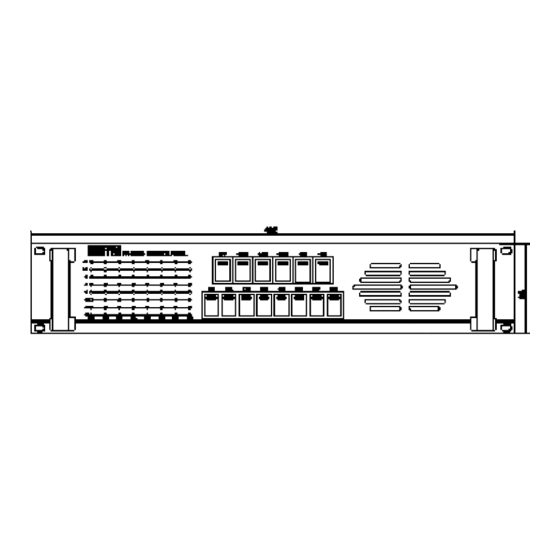
Page 7: Front Panel Controls
Front Panel Controls 1. Level Meter Eight-segment LED meters indicate the output level of each channel. 2. Monitor Level Select Six radio-style switches select the function and level of the front-panel monitor speaker. Switches select between OFF, -24dB, -18dB, -12dB, -6dB and 0dB. 3. -
Page 8: Rear Panel Controls
Rear Panel Controls 1. DC Input Terminals Connect a 24VDC battery source to these terminals. Make certain the red terminal is connected to the battery’s positive (+) side, and the black terminal to the battery’s negative (-) side. 2. Audio Input Terminals (Hot) Connect the positive (+) output terminals of power amplifiers to these inputs for monitoring. -
Page 9: Connection Diagram
PM-9208 Multi-Channel Monitor Panel Connection Diagram... -
Page 10: Schematic Diagram
PM-9208 Multi-Channel Monitor Panel Schematic Diagram... -
Page 11: Specifications
Specifications Outside Inputs LED Monitor Outputs Monitor Speaker Output Power GENERAL Power Source Weight Dimensions Specifications and design subject to change without notice for product improvements. 8-100V or 70V inputs 8 simultaneous outputs 1.5W maximum 24VDC 3.8kg (8.6 lbs) 482 mm(W) 88 mm(H) 280 mm (D) 19 in (W) 3.5 in (H) 11 in (D) - Page 12 Korea and China, and sales and marketing operations located in Japan, Europe, and the U.S.A. With more than 850 employees around the globe, Inter-M is well-poised for further growth and expansion.
Need help?
Do you have a question about the PM-9208 and is the answer not in the manual?
Questions and answers