Advertisement
Quick Links
Advertisement

Summary of Contents for LINE SITE LSL-210
- Page 1 Operating Manual...
-
Page 2: Warning And Caution
WARNING AND CAUTION While the instrument is operating, be careful not to expose your eyes to the • emitting laser beam. Exposure to a laser beam for a long time may be hazardous to your eyes (laser beam: equivalent to Laser Class 2 Standard). Do not try to dismantle the instrument. - Page 3 Introduction Congratulations on the purchase of your Linesite LSL 210 Series Laser. Although simple to use, we recommend that you read this manual before operating the laser. Description The Linesite LSL210 is ideal for general construction, site preparation, vertical alignment and squaring. and other leveling applications. It automatically self-levels in horizontal and vertical modes can be used for manual grade as well.
- Page 4 Horizontal Position Vertical Position When the instrument is set upright, it will emit laser-beam to form a 360-degree horizontal scanning surface and a plumb dot automatically. When set horizontally, it will form a 360-degree plumb scanning surface and a plumb dot.
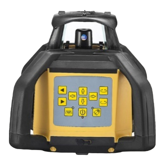
- Page 7 2.3 Main Panel Explanation (1) ON/OFF: Controlling the state of power. (2) Power indicator: When on, the instrument is starting up. Otherwise it is shutting down. (3) Mode indicator: When on, the instrument is leveling manually. When it blinks, it stays in alarm. (The slope of the instrument is out of range). (4) Key of Automatic drift system model: Warns the user for a misaligned device (5) Anti-shocking Alert indicator: When the indicator is blinking slowly, it is in...
- Page 8 2.3 Main Panel Explanation - Continued (7) Directional scanning: Circling knob. Angle of scanning includes 5 levels:0-10°-45° -90°-180° (8) Manual/Automatic: Controlling the mode of leveling. (9) Left-spinning: Making the laser module step-move counter-clockwise when the laser module is power off or it is scanning directionally. (10) Right-spinning: Making the laser module step-move clockwise when the laser module is power off or it is scanning directionally.
- Page 9 3. Directions: 3.1 Battery Please Note - Ni-MH Rechargeable battery pack is pre-installed 4x Alkaline (Size C) pack is included in the case 3.2 Instrument Placement 3.2.1 Horizontal scanning Lay the instrument on the tripod or stable flat surface, or even hang it on the wall.
- Page 10 3.2 Operations 3.3.1 Power Press the Key ON/OFF to bring automatic leveling into function when the power indicator lights. When Power indicator lights, it shows the voltage of the batteries is insufficient. Then the rechargeable batteries need to be charged. Press the Key ON/OFF again to switch off the instrument and power indicator will go out.
- Page 11 3.3.3 Spinning (1) Continuous spinning Press the Key “Rotational speed adjustment” to control the spinning speed of the laser module. If press the key repeatedly, the spinning speed of the laser module will continuously change as follows:0-60-120- 300-600-0 RPM (2) Stepping spinning Locate the Key Speeding-up at speed of 0 r.p.m, the laser module will stop spinning.
- Page 12 will scan directionally. If press the key repeatedly, the angle of scanning of laser module will continuously change as follows: 0°- 10-°45º-90-°180°-0°. (2) Press the Key Left-spinning or the Key Right-spinning to change the direction of scanning. 3.3.5 Slope Adjustment When the instrument is set upright to do horizontal scanning, the slope of X- axis and Y-axis can be set.
- Page 13 1 Slope of X-axis Aim the X1-beam to the direction of the slope required then to adjust. b. Press the Key to move the laser beam up or down. (2) Slope of Y-axis (3) Quit slope adjustment mode Press Manual/Automatic key again. After mode indicator goes off, the instrument then will quit the slope adjustment mode and will self-leveling again.
- Page 14 4. Power When the voltage indicator lights, the batteries need to be charged immediately. Connecting the charger with AC, insert the plug of charger into the plughole at the bottom of the instrument (As depicted above). If the red indicator of charger lights, it shows the batteries are being charged. If the green indicator of charger lights, it shows the recharging has finished.
- Page 15 5. Remote The remote control of the instrument adopts the infrared technique. Aim the aperture of infrared ray to the instrument (as depicted below) to bring remote controlling into function (Available distance: indoor: 20M; outdoor: 15M). The keypad panel includes 9 keys; the indicator on the RC will blink to show the operating signal has been sent out once pressing any key.
-
Page 16: Accuracy Checking
6. Accuracy Checking 6.1 Horizontal-surface Checking (1) Place the instrument at the point of 50m in front of wall (or set a scale plate at the point of 50m away from the instrument), and then adjust the level of the base approximately to aim the X1 to the wall (or scale plate), as depicted below:... - Page 17 (2) After switching on the power, use the laser detector measuring the h1 of X1-beam on the wall or scale plate. (3) Loose the screw of the tripod, turn around the instrument for 180° to measure the h2 of X2-beam on the wall or scale- plate. The method should be the same with h1.
- Page 18 6.2 Horizontal line Checking (1) Place the instrument between two walls with the distance of 30m (or two scale plates with the distance of 30m). (2) Place the instrument according to horizontal setting and then adjust the instrument. (3) Switch on the power, and then measure the middle point of the laser beam on the wall (or scale plate).
-
Page 19: Specifications
7. Specifications Leveling Accuracy (H/V) ±2.4mm at 30m / ±3mm at 30m Leveling Range ±5º Working Range with Receiver (Diameter) depending on working Diameter:650m environment Visible Working Range depending on working environment Spinning Speed 0、60、120、300、600 r.p.m Directional-Scanning Angle 0º、10 º、45 º、90 º、180 º Slope-adjusting Range ±5º(Bi-directional) Laser Diode, Class 2 (IEC60825-... - Page 20 No less than 5hrs (Do not charge RL Charging Time Alkaline battery) Approximately 34 hours Hours in continuous use (Rechargeable) / 25 hrs (Alkaline) RL IP IP 65 Dimension 220mm x 220mm x 210mm Weight 3.1kg Remote IP IP 54 Remote Power Supply Rough Band: 3mm/ Precise Band: Laser Detector Precision...
-
Page 21: Item Checklist
8. Item check list... - Page 23 Notes :...
Need help?
Do you have a question about the LSL-210 and is the answer not in the manual?
Questions and answers