
Summary of Contents for Veralase 202
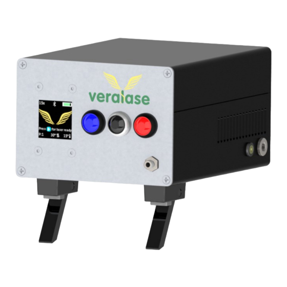
- Page 1 Veralase Veralase Tunable Fiber Coupled Laser User Instructions www.veralase.com Model Number: 202 P a g e...
-
Page 2: Table Of Contents
Veralase Table of Contents Warning ................................ 3 Packaging ..............................4 System Specifications ........................... 5 Device Setup ..............................6 How to use ..............................7 SN500 Temperature vs Wavelength Graph ....................13 SN500 Spot size ............................14 P a g e... -
Page 3: Warning
Veralase Warning 1. Only authorized personnel can use this class 4 laser device. 2. Authorized personnel MUST wear laser safety glass before using the laser. Laser safety glass- es can be found at www.thorlabs.com or www.newport.com 3. Lasers can produce serious injury to the eyes if not handled with care. -
Page 4: Packaging
Veralase Packaging 1) Veralase laser device console 2W 1260-1290nm tunable laser, 105um 0.2NA 2) Power supply 100-240V to 12V 5A 3) Collimation package (optional) 4) Optical patch cable 2m, 200um, 0.22NA SMA-SMA P a g e... -
Page 5: System Specifications
Standard Optical Out- Dia. 6.2 put with collimation package (1) Other models are available for different wavelength, contact Veralase for more infor- mation Electrical / Data Power Adapter Input 100 - 240 50-60 Power Adapter Output Program Parameters... -
Page 6: Device Setup
Veralase Device Setup Connect the fiber patch cable (1) to SMA fiber adaptor on the front panel (2) 2. Connect the collimation package (3) to fiber patch cable (1) 3. Insert the power supply barrel connector (4) into barrel socket on the right side of the device (5) 4. -
Page 7: How To Use
Veralase How to Use Turn on/ Turn off the device Press the Power Button for 1 second to turn on the device Press and hold the Power Button for 2 seconds to turn off the device 2. Passcode screen ... - Page 8 Veralase Estimated treatment count remaining provides user an estimate of how many treatment cycles are left based on current battery. Note the temperature tuning only works when the laser is plugged into external power, and thus, we only recommend using the device when plugged into external power.
- Page 9 Veralase 5. Set temp User can use set temp to adjust the target temperature, use plus or minus to adjust temperature. Once temperature is adjusted, user can see the new set temperate on the bottom of main screen. Adjusting the temperature is done to shift the laser wavelength to the desired wavelength output.
- Page 10 Veralase Stage 1 Time (ms) Stage Power (mW) Time on/pulse Time off/pulse Pulses/trigger (ms) (ms) 1000 1000 This example is extremely simple and is only utilizing a single stage. A more complex example of the 5-stage programming system can be seen on the next page. Stage 1 has a max power of 100 mW, an operation time of 1000 ms (or 1 second), a pause of 1000 ms (or 1 second), and has 1 pulse.
- Page 11 Veralase Stage 1 Stage 2 Stage 3 Stage 4 Stage Stage Power (mW) Time on/pulse Time off/pulse Pulses/trigger (ms) (ms) 1000 1000 1000 1000 1000 1000 After programming one stage, the user may press the green Stage button to go to the next stage.
- Page 12 Veralase 7. Start to treat To start the treatment, the user needs to mount the laser device properly then put the laser into ready mode. Press the Start/Stop Button to set the laser into ready mode, and then press Start/Stop Button again to start the laser program treatment.
-
Page 13: Sn500 Temperature Vs Wavelength Graph
Veralase SN500 Temperature vs Wavelength Graph SN 500 Power level 1 Power level 2 Power level 3 Power level 4 Power level 5 Power Targert 100mW 500mW 1000mW 1500mW 2000mW Temperature Wavelenght (nm) Real Temperature Wavelenght (nm) Real Temperature Wavelenght (nm) Real Temperature Wavelenght (nm) Real Temperature Wavelenght (nm) Real Temperature... -
Page 14: Sn500 Spot Size
Veralase SN500 Spot Size No collimation Power (mW) Distance (mm) fwhm 1/e2 Distance (mm) fwhm 1/e2 half angle (FWHM) half angle (1/e2) half angle(1%) 35.12 56.69 92.04 82.47 131.6 186.3 8.021449809 12.56834295 15.67070519 39.07 59.89 96.63 86.57 133.8 192.5 8.046528657 12.40579201...
Need help?
Do you have a question about the 202 and is the answer not in the manual?
Questions and answers