
Summary of Contents for CeYeKo LUDP
- Page 1 Tech ULTRASONIC LEVEL SENSOR User’s Manual LUDP / LUDR Copyright © CeYeKo Technology 2021 LUDx_M_V0.0...
-
Page 2: Preface
something wrong or incorrect, please contact us. This product is forbidden to use in explosion-proof occasions. Versions : LUDP Compact Version LUDR Remote Version D i s c l a i m e r After opening the box, please confirm the package contents before starting the operation. -
Page 3: Instructions
Illustration Description: This is an important reminder, please read it carefully and follow the require- ments strictly. This is a general reminder, please read it carefully so as not to cause trouble in use Page 3 www.ceyeko.com... -
Page 4: Table Of Contents
Chapter 8: Fault Causes at Site According to Echo Pattern ………………………… 48 8.1 Resonance …………………………………………………………………………………… 8.2 Liquid Enters the Blind Area of Ultrasonic Level Gauge ………………… 8.3 Electromagnetic Interference ……………………………………………………… 8.4 Effects of Connecting Pipe to Measurement …………………………………… Chapter 9: Modbus Communication Protocol V1.4 Version ………………………… Page 4 www.ceyeko.com... -
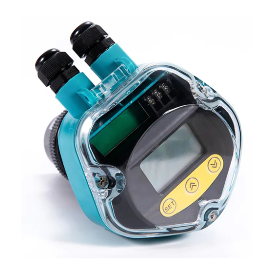
Page 5: Chapter 1: Product Introduction
There are three buttons on the panel, via which the meter can be adjusted. The measured values are displayed on the LCD screen after the adjustment. Enter Menu Item Exit Menu Item Confirm Parameter Modification Move Cursor Modify Parameter Choose Menu Item Page 5 www.ceyeko.com... -
Page 6: Enter The Menu
The menu modes include expert setting mode and simply setting mode. The menu query table of simple setting mode is as shown in the below. The menu query table of expert setting mode is shown in “VI. Menu Interface & Operating Instructions: ”. Page 6 www.ceyeko.com... -
Page 7: Select Measuring Mode
Fig. 1.1 Distance Measurement Mode; measure the distance from probe emision surface to water surface, output 4-20 mA corresponds to the variation of distance. Fig. 1.1 Diagram of Distance Measurement Page 7 www.ceyeko.com... -
Page 8: Anti-Interference Measures
It must be installed separately through a metal pipe, or instal- led away from the power line and power line. Under the premise of not being installed through the pipe, the distance from the power line and power line at least 1 meter Page 8 www.ceyeko.com... -
Page 9: Chapter 3: Main Technical Parameter
Ambient Display instrument: -20~+60ºC Temperature Probe: -20~+80ºC Communication RS485, RS232 communication (optional) Ingress Protection Display Instrument: IP65, Probe: IP68 100m available, standard Probe Cable None configuration: 10m Probe Select type based on Installation measuring range and probe Page 9 www.ceyeko.com... -
Page 10: Power Consumption
The integrated type with two-wire system is powered by 24V Power power supply. It cannot be equipped with relay and its electricity Consumption consumed is 20mA. (Compact Type) Specific power consumed is shown in below: 24×20mA=0.48W for integrated type without relay; Page 10 www.ceyeko.com... -
Page 11: Chapter 4: Installation Guide
C h a p t e r 4 : I n s t a l l a t i o n G u i d e 4.1 Installation Dimension of Level Meter 4.1.1 Standard Remote Type Ultrasonic Level Meter: Structural Drawing 4.1.2 Enhanced Compact Type Ultrasonic Level Meter: Side Picture Front Picture Page 11 www.ceyeko.com... - Page 12 Tech Page 12 www.ceyeko.com...
-
Page 13: Installation Guide
18 meters from the probe. Try to make the axis of the sensor perpendicular to the surface of the medium, and avoid any other objects within the emission angle. Such as: pipes and brac- kets. Page 13 www.ceyeko.com... -
Page 14: Select Measuring Range
Soft (such as pulverized Use not coal, cement and coal 40...60dB 99~99.9% recommended ash) Attenuation Attenuation Magnification of With Dust Multiple Percentage Measuring Range None Magnification is unnecessary 1 times of the Little measuring range Page 14 www.ceyeko.com... - Page 15 Temperature difference between probe and medium surface ≤40ºC 5...10dB Total minimum: 15dB maximum: 40dB Under such circumstances, if the actual maximum measuring range is 5m, ultrasonic level meter with measuring range of 50m shall be selected for the measurement. Page 15 www.ceyeko.com...
-
Page 16: Installation Of Thread At The Bottom
03.Align the transducer with flange hole 04.Place the transducer in flange hole 05.See from the flange bottom 06.Place a spacer of the same inner diameter under the flange 07.Tighten nuts to fix the transducer 08.Transducer installed Page 16 www.ceyeko.com... -
Page 17: Top Thread Installation-Hoisting Installation
≥100mm and inner wall is smooth and free of burr and bulges, the measurement can be carried out if the emitting surface of installed probe is 3cm be- low the flange undersurface. Flange installation in a short connecting pipe Page 17 www.ceyeko.com... - Page 18 Probe installation on nipple joint Hoisting thread connection at the remo- te type probe top Similarly, the remote type sensor can be installed via top hoisting thread and the di- mensions of hoisting thread include M30×1.5, M32×1.5 and M38×1.5. Page 18 www.ceyeko.com...
- Page 19 200mm 150mm joint shall be polished. 250mm 180mm The connection of connecting pipe and tank 300mm 220mm top shall be outwards polished at an oblique angle of 45º. 400mm 280mm Page 19 www.ceyeko.com...
- Page 20 As the open container has no focusing effect, the sensor can be installed in the middle of the container. Installation on open container – with support at the top middle part Page 20 www.ceyeko.com...
- Page 21 The measuring casing shall be soaked in the medium all the time, which can ensu- re the accurate measurement within the measuring casing. Page 21 www.ceyeko.com...
-
Page 22: Solid Measurement
Compact type sensor installed on container flange Remote type sensor ins- talled on container flan- Page 22 www.ceyeko.com... -
Page 23: Installation Via Nipple Joint
During installation for material piles in the open air, several meters are required for the measurement of large material pile in the open air. The meters can be fixed on the hoist frame and sensor probe shall be aligned to the medium surface. Page 23 www.ceyeko.com... -
Page 24: How To Extend The Connecting Pipe For Measurement
The bottom of the connecting tube should be cut at a 45° bevel to avoid strong ec- hoes at the bottom of the connecting tube. At the same time, the ratio of the height of the connecting tube to the inner diameter of the connecting tube should be ≤5:3. Page 24 www.ceyeko.com... - Page 25 120mm burr and bulges and vertical and the weld joint shall be polished. The connection of 250mm 150mm connecting pipe and tank top shall be 300mm 180mm outwards polished at an oblique angle of 45º. 400mm 240mm Page 25 www.ceyeko.com...
- Page 26 (2) How to extend the connecting pipe for solid measurement Measurement of solid medium is different from that of liquid. The conical extended connecting pipe with an angle of 25°~30° shall be used. Extended connecting pipe for solid medium measurement Page 26 www.ceyeko.com...
-
Page 27: Installation Should Avoid False Echo
If the upper surface of object at the lower part of the container is a plane, the inlet for various media must be covered with a deflector set at certain angle. Flat-top bulge at the bot- tom of the container – deflector required Page 27 www.ceyeko.com... - Page 28 The sensor shall not be installed in or above the charging feedstock flow and it shall be kept from the feed inlet for certain distance. Sensor shall not be ins- talled in or above the charging feedstock flow Page 28 www.ceyeko.com...
- Page 29 If the objects with elevation difference at the pool bottom are exposed in case of low water level, the edge shall be covered with a deflector. Barriers at the pool bottom – reflect with a deflector Page 29 www.ceyeko.com...
- Page 30 Other measuring meters can also be used, such as radar liquid level meter or mag- netostrictive liquid level meter. Occasions when bubbles are generated Page 30 www.ceyeko.com...
- Page 31 The error will add by 2-4% on the basis of original measurement accuracy. Therefore, sun louver shall be installed to solve the problem. Great temperature change – add sun lou- ver or meter box Page 31 www.ceyeko.com...
-
Page 32: Electric Wiring Diagram
The cables connecting the sensor and main equipment shall not be put in a trunking with any alternating current. If it can not be prevented, the cables of sensor shall be protected by a cable conduit to completely shield the electromagnetic interference caused by alternating current. Page 32 www.ceyeko.com... -
Page 33: Electric Wiring Diagram Single-Probe Remote-Type
To ensure the default state of relay is “normally open”, RLlnA and RLnB shall be con- nected. RlnA and RLnC are normal closed. To ensure the default state of relay is “normally closed”, RLlnA and RLnC shall be connected. Page 33 www.ceyeko.com... - Page 34 485 Connection: 485A connection "TXD/485A" terminal, 485B connection "RXD/485B" terminal. 232 Connection: TXD connection "TXD/485A" terminal, RXD connection "RXD/485B" terminal. 232 ground connection "mA-/GND" terminal. 232 Output Wiring: Relay output connection method: Take “Relay 1” as a example, others are same Page 34 www.ceyeko.com...
-
Page 35: Wiring Diagram Of Compact Type
4.4.2 Wiring Diagram of Compact Type : Enhanced Compact type with four-wire system Electric Wiring Diagram of Enhanced Integrated Type with Four-wire System 24VDC Power Supply Wiring Diagram of Four wire Sys- 220VAC Power Supply Wiring Diagram of Four wire System Page 35 www.ceyeko.com... - Page 36 Tech Enhanced Compact type with two-wire system Electric Wiring Diagram of Two-wire System Wiring Diagram of Two-wire Ampere Meter Diagram of Two-wire Page 36 www.ceyeko.com...
-
Page 37: Chapter 5: Settings
4~20mA. Output current is in direct proportion to the material level. The interface of ultrasonic level meter under operating mode is as follows: Note: language selection, hold the buttons at the same time to switch Two-wire (English) Four-wire (English) Page 37 www.ceyeko.com... -
Page 38: Chapter 6: Menu Interface & Operating Instructions
Menu interface of expert setting mode and operating instructions are shown below: ❶ Press SET in operating mode interface to enter in the “Mode selection ”main me- ❷ Descriptions of the main menu items: Interface of the main menu with unlocked parameters: Page 38 www.ceyeko.com... - Page 39 Unlock: unlock, and all parameters of the menu can be changed randomly. All-lock: for the conditions, the changes can be made only after entering password. If the parameters are locked, press SET and enter in the unlocking interface for parameter locking: Page 39 www.ceyeko.com...
- Page 40 Distance Measurement: the display value is the distance from the probe to the sur- face measured; Material Level Measurement: the display value is the distance from the bottom to liquid surface, i.e. liquid level height. The factory default is material level measurement. Page 40 www.ceyeko.com...
- Page 41 Current Set (Set Current): set the output current after wave loss, which shall be more than 3.6mA and less than 22mA, and become invalid in case of remaining/ minimum/maximum values on reselection. The factory default is 3.6mA. Page 41 www.ceyeko.com...
- Page 42 Threshold S(Short threshold value): to be modified under the guidance of pro- fessional technical personnel only. Sensitivity L(Long sensitivity): to be modified under the guidance of Professio- nal technical personnel only. Threshold L(Long threshold value): to be modified under the guidance of pro- fessional technical personnel only. Page 42 www.ceyeko.com...
- Page 43 For Water Supply: when water level is below 1m, water pump start to feed water; when water level rises to 5m, water pump stop feeding water. Detailed settings are shown below: Alarm 1 mode: low-level alarm. Alarm 1 value: 1.00m; alarm 1 return difference: 4.00m. Page 43 www.ceyeko.com...
- Page 44 Tech Page 44 www.ceyeko.com...
- Page 45 1 so that 4mA correction can be realized. 20mA Adjust (20mA correction): keep modifying the value until the actual output current reaches 20mA. Factory default is 7200. Voltage (Reference level): input the measured voltage at relevant test point. Factory default is 5.00. Page 45 www.ceyeko.com...
- Page 46 Factory Reset: Yes: restore factory settings so that setting error can be re- solved. No: exit. Factory default is No. System Reset: Yes: restore system settings. No: exit. Factory default is (Do Not Modify This Item.) Page 46 www.ceyeko.com...
-
Page 47: Chapter 7: Trobleshooting
6.The liquid level is in a 6.Raise the installation posi- blind area. tion of probe. 7.The measured medium is 7.Check whether the medium soft powder or there is foam is powder. If so, consult the on liquid surface. manufacturer. Page 47 www.ceyeko.com... -
Page 48: Chapter 8: Fault Causes At Site According To Echo Pattern
Page 48 www.ceyeko.com... -
Page 49: Liquid Enters The Blind Area Of Ultrasonic Level Gauge
After we raise the installation position of probe to make the distance from the hig- hest water level to the emitting surface of probe be greater than 0.50 (blind area), we find that the echo close to probe on the left changes. Page 49 www.ceyeko.com... -
Page 50: Electromagnetic Interference
Show elect- romagnetic interference. The three figures in the first row and the first two figures in the second row below the base line are all 0, meaning that the echo is covered by the wave from probe. Page 50 www.ceyeko.com... - Page 51 Although there is interfe- rence of frequency converter, the data measured at site is correct as the echoed sig- nal intensity on water surface is obviously stronger than the interference signal of frequency converter. Page 51 www.ceyeko.com...
-
Page 52: Effects Of Connecting Pipe To Measurement
In the figure above, the base line of echo pattern is very wide, which is caused by signal amplification by connecting pipe. The echo enclosed by circle is real echo whi- le the part enclosed by frame is wide base line. Page 52 www.ceyeko.com... -
Page 53: Chapter 9: Modbus Communication Protocol V1.4 Version
1st byte adr: slave address code (=001~254) 2nd byte 03h: read register value function code 3rd, 4th byte: Register start address to be read 5th, 6th byte: number of registers to read 7th, 8th byte: crc16 check from byte 1 to 6 Page 53 www.ceyeko.com... - Page 54 4th, 5th byte: crc16 check from byte 1 to 3 Function code 06h: Write a single register value The host sends: Register Register Data high Data low Crc code Crc code address address byte byte low byte high byte high byte low byte Page 54 www.ceyeko.com...
- Page 55 10, 11 N, N+1 Crc code low Crc code high Register data 1 Register data 2 Register data m byte byte Page 55 www.ceyeko.com...
- Page 56 1st byte adr: slave address code (=001~254) 1st byte 90h: Write register value error function code 3rd byte information code: see information code table 4th, 5th byte: crc16 check from byte 1 to 3 Page 56 www.ceyeko.com...
- Page 57 Reference zero point (2 Range high (2 bytes 002A 002B bytes high first) high first) Low range (2 bytes Set current (2 bytes 002C 002D high first) high first) Blind zone setting (2 002E 002F Reserved bytes high first) Page 57 www.ceyeko.com...
- Page 58 Baud rate mode of 0062 0063 Reserved operation 0064 Reserved 0065 Reserved 0066 Reserved 0067 Reserved 0068 Reserved 0069 Reserved Remarks: ❶ 2 bytes hexadecimal notation, high order first: (Note: floating point numbers are multiplied by 100, expressed in hexadecimal) Page 58 www.ceyeko.com...
- Page 59 In the same area, you can read (or write) a parameter in a single time, or you can read (or write) all the parameters in the area, and do not allow read and write ope- rations across the area. Page 59 www.ceyeko.com...
- Page 60 ❹ All reserved registers are currently undefined and are reserved for future upgra- de compatibility. Information Code Table Information code Express meaning Illegal function code Illegal data address Illegal data value Crc16 checksum error Received correctly Receive error Parameter error Page 60 www.ceyeko.com...
- Page 61 Tech CeYeKo Fluid Measurement Technology www.ceyeko.com Copyright © CeYeKo Technology 2021 LUDP / LUDR Ultrasonic Level Sensor Manual LUDx_M_V0.0...
Need help?
Do you have a question about the LUDP and is the answer not in the manual?
Questions and answers