
Summary of Contents for Hoopo HOOPOSENSE 502B1000-2A
- Page 1 HOOPOSENSE LORA DEVICE 502B1000-2A User Manual hoopo Systems Ltd.| 5 Ayalon Street, Ramat Hasharon...
-
Page 2: Table Of Contents
Mechanical ........................2 Electrical ........................5 Connectivity ......................5 Radio Compliance Statement ..................5 Battery Installation/replacement ................7 Top Cover Removal ...................... 7 Batteries Installation ....................8 Top Cover replacement ....................11 hoopo systems ltd. – hoopoSense Installation and connectivity V 0.102... -
Page 3: General
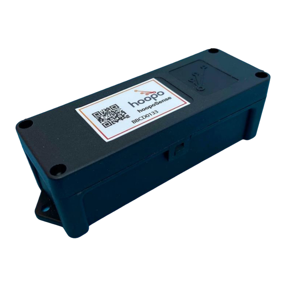
The hoopoSense devices are part of a tracking system that consists several FPX3 LoRa gateways and a cloud based application server. The hoopoSense device transmits various environmental and location parameters via LoRa or cellular communication channels. 3.1 Mechanical 3.1.1 hoopoSense mechanical outline hoopo systems ltd. – hoopoSense Installation and connectivity V 0.102... - Page 4 Figure 1: hoopoSense with spacer outline drawing hoopo systems ltd. – hoopoSense Installation and connectivity V 0.102...
- Page 5 Figure 2: hoopoSense with no spacer outline drawing hoopo systems ltd. – hoopoSense Installation and connectivity V 0.102...
-
Page 6: Electrical
However, there is no guarantee that interference will not occur in a particular installation. If this equipment does cause hoopo systems ltd. – hoopoSense Installation and connectivity V 0.102... - Page 7 -Consult the dealer or an experienced radio/TV technician for help. Changes or modifications to this equipment not expressly approved by the party responsible for compliance (hoopo Systems Ltd.) could void the user’s authority to operate the equipment. WARNING! To comply with FCC RF exposure compliance requirements, the device should be located at a distance of at least 20 cm from all persons during normal operation.
-
Page 8: Battery Installation/Replacement
6 Battery Installation/replacement 6.1 Top Cover Removal 6.1.1 Remove the four top cover screws with a #1 phillips screwdriver. 6.1.2 Release both side latches using a flat screwdriver. hoopo systems ltd. – hoopoSense Installation and connectivity V 0.102... -
Page 9: Batteries Installation
6.2 Batteries Installation 6.2.1 Group the batteries in pairs using the supplied plastic tubes as depicted in the following picture: 6.2.2 Please note the inscribed polarity on the bottom of the enclosure. hoopo systems ltd. – hoopoSense Installation and connectivity V 0.102... - Page 10 6.2.3 Place the nylon tab at the (+) pole. 6.2.4 Insert the bottom batteries pair; the (-) end first. 6.2.5 Press/slide down the batteries in-place as depicted in the following picture: hoopo systems ltd. – hoopoSense Installation and connectivity V 0.102...
- Page 11 Note: Both batteries pairs are installed in parallel, (-) on top (-) and (+) on top (+) 6.2.7 Press/slide down the batteries in place. 6.2.8 Pull out the nylon tab slider. hoopo systems ltd. – hoopoSense Installation and connectivity V 0.102...
-
Page 12: Top Cover Replacement
6.3.2 Place and tight the top cover screws. Do not overtight. Note: Tightening torque 1Nm maximum 6.3.3 In case one or both of the side latches are not fully engaged as depicted below: hoopo systems ltd. – hoopoSense Installation and connectivity V 0.102... - Page 13 6.3.4 Apply pressure at the center of the top cover until it “cliks” in place, if needed repeat for both side latches. hoopo systems ltd. – hoopoSense Installation and connectivity V 0.102...
Need help?
Do you have a question about the HOOPOSENSE 502B1000-2A and is the answer not in the manual?
Questions and answers