Table of Contents
Advertisement
Quick Links
Advertisement
Table of Contents

Summary of Contents for medical bees MB1-17-20 Series
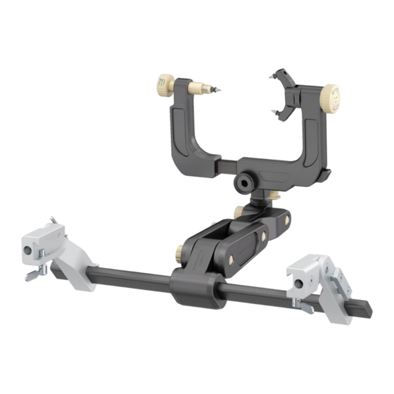
- Page 1 0483 Instructions for Use CT/ MRI compatible MF-Headrest/ Cranial Stabilization and Fixation System MB1-17-20X-XX Medical Bees GmbH Friedrich-Wöhler-Straße 13 78576 Emmingen-Liptingen Germany CT/ MRI compatible MF-System Date Revision Page 21 October 2021 IFU GA-008-02 Seite 1 von 37...
-
Page 2: Table Of Contents
0483 Content Conformities ........................5 Guidelines and norms....................5 CE conformity ......................5 General Safety Information ................... 5 Symbols used for safety information ................ 5 Proper handling ....................... 6 Permitted user ......................6 Basic Information ......................6 Warranty and liability ....................6 Obligations of the purchaser .................. - Page 3 0483 Connecting to Maquet OR-table (CT-/ MRI compatible system) ......25 Skull clamp ......................27 Horseshoe .......................29 Function and safety inspections ................30 Before clinical use ...................30 After clinical use ....................30 Care ..........................31 Preparation for decontamination................31 Pre-cleaning process ....................31 Cleaning / disinfection ....................31 Manual cleaning process .................31 Automatic cleaning / disinfection process ............32 Inspections ......................32...
- Page 4 0483 Preface Dear reader, These instructions for use provide information on the following aspects of the Premium MF-Headrest System: • safety • mounting/ assembly • usage • maintenance We continuously update our instruction manuals. Your suggestions concerning this manual are welcome since they will help us make the manual even more user-friendly.
-
Page 5: Conformities
0483 1 Conformities 1.1 Guidelines and norms Description Guidelines and norms MF- CT/ MRI compatible Headrest System COUNCIL DIRECTIVE 93/42/EEC of 14 June 1993 1.2 CE conformity The MF- CT/ MRI compatible Headrest System conforms to the basic requirements of the applicable guideline and the corresponding norms of the Council of the European Union. -
Page 6: Proper Handling
0483 Exclusion of liability: This symbol points out exclusions of liability of the manufacturer. Such disclaimers result if the purchaser or user does not employ the device properly or fails to follow the instructions. You must carefully read, observe and follow the safety information furnished in this instruction manual! 2.2 Proper handling The device may only be used by trained staff. -
Page 7: Obligations Of The User
0483 3.3 Obligations of the user All users of the device shall confirm in writing that they have read and fully understood the safety information and the instructions contained in this manual 3.4 Usage as per instructions The Headrest System is designed and built according to the latest technical developments and to approved safety standards. -
Page 8: Components
0483 4.2 Components The CT-Headrest System consists of the following components: Description: Item-No. Table adapter with connecting arm MB1-17-200-31 + MB1-17-200-15 Swivel Adaptor MB1-17-200-26 (MB1-17-200-25) Skull Clamp MB1-17-200-40 MB1-17-200-35 Horseshoe headrest The system components consist of the following main parts: Table adapter with connecting arm •... -
Page 9: Swivel Adaptor
0483 Swivel Adaptor • swivel base • two retaining ring units • clamping screw 2x M24 1x M16 Fig. 2 Swivel Adaptor, general view Skull Clamp • Skull Clamp base • Skull Clamp extension assembly torque screw with Skull Pin holder (rotates 360 degrees) Fig. -
Page 10: Horseshoe
0483 Horseshoe • Horseshoe base • clamping screw 2x M24 1x M16 Fig. 4 Horseshoe with gelpads general view 4.3 Mounting of additional parts We recommend using the following components with the Headrest System (refer to instruction manual Skull Pins): Description Item number Skull Pins stainless steel, Adult... -
Page 11: Technical Specifications
0483 4.4 Technical specifications Type of device: MF-CT Headrest System Weight: Table adapter with connecting arm 6250 g Swivel Adaptor 500 g Skull Clamp 1700 g Horseshoe 3450 g Material PEEK, POM C aluminum cast, stainless steel (table adapter) Dimensions see outline drawing The two end brackets of the Table adapter with connecting arm are equipped with an internal isolation to prevent electrical stray currents when the Table adapter with connecting arm is... - Page 12 0483 Fig. 5 Outline drawing Table adapter with clamp mount Fig. 6 Outline drawing Swivel Adaptor CT/ MRI compatible MF-System Date Revision Page 21 October 2021 IFU GA-008-02 Seite 12 von 37...
- Page 13 0483 Fig. 7 Outline drawing Skull Clamp CT/ MRI compatible MF-System Date Revision Page 21 October 2021 IFU GA-008-02 Seite 13 von 37...
- Page 14 0483 Fig. 8 Outline drawing Horseshoe CT/ MRI compatible MF-System Date Revision Page 21 October 2021 IFU GA-008-02 Seite 14 von 37...
- Page 15 0483 Type of device: CT-/ MRI compatible Headrest System Weight: Table adapter (Maquet) 2640 g Skull Clamp 1700 g Horseshoe 3450 g Material PEEK, POM C Dimensions see outline drawing Fig. 9 Outline drawing Table adapter (Maquet) CT/ MRI compatible MF-System Date Revision Page...
-
Page 16: Mounting
0483 5 Mounting 5.1 Mounting of the Table adapter with connecting arm To mount the Table adapter with connecting arm 1 Position the connecting arm assembly with the locking lever at the center of the connecting bar/rod. 2 Place the adjustable end bracket onto the left end of the connecting tube. 3 Loosen the screws of the connecting arm 4 Connect the transitional member to the connecting arm assembly. -
Page 17: Mounting Of The Swivel Adaptor
0483 5.3 Mounting of the Swivel Adaptor Mounting the Swivel Adaptor to the Table adapter with connecting arm: Mount the Swivel adaptor to the transitional member of the Table adapter with connecting arm Screw the retaining ring at the transitional member and the retaining ring at the Swivel Adaptor together. -
Page 18: Usage And Handling
Lock the Swivel Adaptor torque screw by applying an adequate force/ pressure. 6.3 Using the Skull Clamp The Skull Clamp is a component of the complete medical bees MF-System. It holds the Skull Pins which enter the patient’s head. This allows a fully flexible adaptation of the position of the MF-System to the patient’s position. -
Page 19: Using The Horseshoe Headrest
0483 6.4 Using the Horseshoe Headrest The Horseshoe Headrest is one part of the complete system. It serves as a convenient headrest for the patient during surgery in lateral or vertical positions. The patient's head is fixated in several steps: Adjust the Base Unit and the Swivel Adaptor Horseshoe and the Horseshoe Headrest to the patient's position. - Page 20 0483 Fixate the patient’s head with the Skull Pins and the Skull Clamp and ensure all adjustable joints are then tightened and secured. Danger: The user decides which type of fixation and what clamping force are required, based on the thickness of the skull and the bone structure.
- Page 21 0483 Fig. 11 Clamping force Note: Before starting the case make sure that the rings are showing (see Fig. 10). When applying pressure less rings become visible. The higher the force, less rings become visible and more pressure is applied to the head. CT/ MRI compatible MF-System Date Revision...
- Page 22 0483 Danger: The MF-System is temporarily destabilized when you loosen handles and fastening screws. Therefore: Ensure that all handles and fastening screws at the device are properly locked prior to each clinical application of the system. Danger The MF-Skull Clamp may cause damage to the patient’s skull. The head may fall out of the Skull Clamp or the Skull Pins may break through into the brain if using an incorrect clamping force.
-
Page 23: Set-Up/ Assembly/ Instructions For Use For Ct-System
0483 6.6 Set-Up/ Assembly/ Instructions for use for CT- System Connection to OR-table 1. Remove table connection with fixed table adapter and move connecting arm onto the rod (with the side of the adjustment screws). 2. Place the connecting arm approximately in the centre of the rod. - Page 24 0483 7. Adjust the connecting arm. 8. Screw the swivel adapter to the connecting arm. 9. To have additional security and stability, the screws should be tightened with these tools. 10. Test this assembly to see if it is stable by pulling/pushing/turning.
-
Page 25: Connecting To Maquet Or-Table (Ct-/ Mri Compatible System)
0483 Connecting to Maquet OR-table (CT-/ MRI compatible system) screws table Swivel plate Clamping bolt Screw 3 Screw 2 Screw 1 Swing arm plate Clamping lever 2. Table adapter is fixed to the operating table via these 4 screws and nuts. If there is a thread in the table, the screws are screwed directly into the table. - Page 26 0483 8. Loosen Scres 1 by turning it counterclockwise to be able to swivel the swing arm plate freely around the horizontal axis. Lower turning position. Upper turning position. (Tighten Scres 1 by turning clockwise to desired position). 9. Loosen Screw 2 by turning it counterclockwise to be able to swivel the swing arm plate freely around the horizontal axis.
-
Page 27: Skull Clamp
0483 Skull clamp 11. Screw the clamping screw into the movable arm of the skull clamp. Correct 12. Please note: do not screw in too far, otherwise no additional pressure can be built up. 13. Open/ Close Symbol By turning the beige twist handle, the pin holder can be rotated 360°. - Page 28 0483 16. Attach the skull clamp to the patient´s skull. Place the completely opened skull clamp in the desired position and compress the skull holder. Important: the skull clamp is not connected to the lower part (swivel adapter, table connector) Readjust the pressure on the skull using the spring-loaded tensioning screw.
-
Page 29: Horseshoe
0483 Horseshoe 11. The movable part of the headrest holder is placed on the rod. 12. The beige screw handle is screwed into the movable headrest holder. 13. The extension arm is screwed to the fixed the headrest holder. 14. The gel pads are clipped onto the horseshoe of the headrest. -
Page 30: Function And Safety Inspections
0483 6.7 Function and safety inspections The user is responsible for function and safety inspections before and after each clinical use. Exclusion of liability: The manufacturer shall not be liable for damages resulting from improper function and safety inspections or failure of the user to perform such inspections. Danger: Check all fastening screws and the stability of the Headrest System before and after each clinical use. -
Page 31: Care
0483 7 Care Important: Attention, only the skull clamp, swivel adapter may be treated according to the following steps! All other components may only be cleaned by wipe disinfection! 7.1 Preparation for decontamination The devices shall, where possible, be dismantled before subsequent processing stages or be submitted to reprocessing in an opened condition. -
Page 32: Automatic Cleaning / Disinfection Process
0483 Manual drying Manual drying with a disposable lint-free cloth. In order to avoid as much water residues in cavities as possible, we recommend blowing them with sterile, oil-free compressed air. The devices must not be heated above 140°C. Automatic cleaning / disinfection process (Washing machine, a washer-disinfector acc. -
Page 33: Maintenance And Care Of Instruments
0483 Maintenance and care of instruments Allow the devices to cool down to room temperature. “Maintenance” means the application of oil or instrument milk (emulsion of white oil in water). Devices with articulated joints or locks (forceps, clamps, etc.) or with metal sliding surfaces (punches, etc.) shall be treated with maintenance paraffin oil-based agents. - Page 34 0483 CT/ MRI compatible MF-System Date Revision Page 21 October 2021 Seite 34 von 37 IFU GA-008-02...
-
Page 35: Maintenance And Repair
The next maintenance date is signed on the skull clamp, at which time only the skull clamp should be sent to medical bees GmbH. Maintenance is possible a maximum of 3 times. Fig. 12 signed maintenance date... -
Page 36: Maintenance To Be Performed By The Purchaser
0483 8.3 Maintenance to be performed by the purchaser The Table adapter with connecting arm is adjustable in all directions. Frequent realignment of the Table adapter with connecting arm may cause the adjustable parts to loosen. Make sure that all beige screws can tighten firmly. 9 Environmentally Compatible Disposal The purchase or user is responsible for rendering the device unusable if it is no longer to be applied (prevention of misuse). -
Page 37: Seite 2 Von
0483 10 Appendix 10.1 Manufacturer information Manufacturer medical bees GmbH Friedrich-Wöhler-Str.13 D – 78576 Emmingen Phone +49 7465 / 929831 0 +49 7465 / 929831 1 E-mail info@medical-bees.de Internet http://www.medical-bees.de When you do not reach us directly with a reportable event, then write an email to us, using the following email address: Meldung@medical-bees.de...
Need help?
Do you have a question about the MB1-17-20 Series and is the answer not in the manual?
Questions and answers