Table of Contents
Advertisement
Advertisement
Table of Contents

Summary of Contents for FKM FKM3016C
- Page 1 Model No. FKM3016C...
-
Page 3: Table Of Contents
Contents Before Use --------------------------------------------------------------------------------------------- 1. Preparations before Use ------------------------------------------------------------------------ 2. Safety Instructions --------------------------------------------------------------------------------- 3. Icon Explanation ------------------------------------------------------------------------------------ 4. Maintenance ----------------------------------------------------------------------------------------- Product Description ------------------------------------------------------------------------------- 1. Part Name --------------------------------------------------------------------------------------------- 2. Switches and Keys Instructions --------------------------------------------------------------- 3. LCD Display ------------------------------------------------------------------------------------------- About the Instrument ----------------------------------------------------------------------------- 1. - Page 4 18. Temperature Measurement ---------------------------------------------------------------- Non-contact Voltage(NCV) Detection ------------------------------------------------ Battery & Test Leads Replacement ------------------------------------------------------- 1. Replace the Battery ------------------------------------------------------------------------------- 2. Replace the Test Leads ------------------------------------------------------------------------- Accessories --------------------------------------------------------------------------------------------- Disclaimer ---------------------------------------------------------------------------------------------- Warranty ------------------------------------------------------------------------------------------------ Contact Us ---------------------------------------------------------------------------------------------...
-
Page 5: Before Use
Before Use Warning To avoid electric shock or injury, please read the "Safety Instructions" and all relevant parts before using this product. In order to give full play to the functions of the instrument and ensure safety, please read and follow this manual carefully. This instrument strictly follows GB/T 13978-92 generic specification for digital clamp meter, in accordance with GB4793.1-1995(IEC-61010-1, IEC-61010-2-032)electronic measuring instruments safety requirements, and belongs to the class-two of pollution. -
Page 6: Safety Instructions
2. Safety Instructions Use the instrument as described in the manual and within the correct ranges. During measurement, do not exceed the indicated value of the protection range of each test. When measuring circuit, do not touch the test leads tip (the metal part). During the measurement, if the measured voltage is higher than 60V DC or 30V AC (RMS), keep fingers behind the finger guards at all times. -
Page 7: Maintenance
4. Maintenance Please do not attempt to open the bottom shell to adjust or repair the instrument. Such operations can only be performed by technicians who fully understand the instrument and the danger of electric shock. Remove the test leads from the circuit under test before opening the bottom shell of the instrument or the battery cover. -
Page 8: Part Name
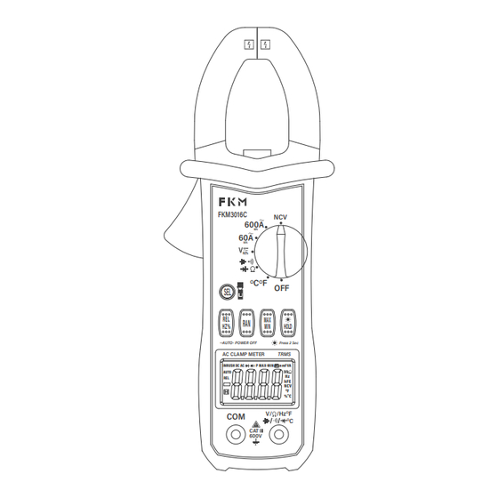
1. Part Name Current Sensing Clamp: for current measurement Flashlight Panel Trigger Function Keys (SEL) Relative Value / Frequency / Duty Cycle Switching Key (REL/Hz%) Auto/ Manual Range Switching Key (RAN) LCD Display Screen COM Terminal INPUT Terminal (for Resistance, Capacitance, Voltage, Frequency, Diode and Continuity) Maximum / Minimum Button (MAX/MIN) Data Hold Switch / Backlight Button ( HOLD... -
Page 9: Switches And Keys Instructions
2. Switches and Keys Instructions Key: For data holding or backlight control. HOLD SEL Key: For function switching. RAN Key:Switch between manual and automatic measurement functions. REL/Hz% Key: For relative measurement / frequency measurement / duty cycle mea- surement. MAX/MIN Key:To switch the maximum and minimum measurement functions. OFF:Used to turn off... -
Page 10: About The Instrument
About the Instrument The instrument shall specify the period of one year, and needs to be recalibrated under the conditions of 18 ℃ (64.4℉) ~ 28 ℃ (82.4℉) and relative humidity less than 75%. 1. Overview of the Instrument Automatic Measurement and Manual Measurement Overload Protection The Maximum Voltage Allowed between the Measuring Terminal and Earth: 1000V DC or 750V AC... - Page 11 2.1 True RMS For the measurement of sine wave signal, the true RMS measurement method has less error than the traditional average response method. The RMS meter can accurately measure the sine wave signal, but if the measured signal is not input in the AC function (in the AC voltage function, the input terminal is short-circuited), the clamp meter may display a value between 1 and 50.
- Page 12 2.4 AC Voltage Range Resolution Accuracy 0.001V ±(1.0% + 5) 0.01V 600V 0.1V ±(1.2% + 5) - Input Impedance: 10MΩ - Maximum Input Voltage: 600V AC(Effective value)or 600V DC - Frequency Range: 40 ~ 1000Hz Notice: In the small voltage range, if the test leads are not connected to the circuit under test, the meter may have a pulsating reading.
- Page 13 2. 6 Duty Cycle Range Resolution Accuracy 0.1 ‒ 99.9% 0.1% ±3.0% 2.6.1 Through A file (From the clamp head) : - Frequency Response: 10 ~ 1kHz - Input Current Range: ≥ 20A AC (Effective value) - Maximum input current: AC 1000A 2.6.2 Through the V file: - Frequency Response: 10 ~ 10kHz - Input Voltage Range: ≥...
- Page 14 2.8 Continuity Test Range Resolution Accuracy If the resistance of the tested circuit is less than 50, the buzzer in the Ω meter may sound. If it is less than 10, the buzzer will definitely sound. - Overload Protection: 250V DC or AC (Effective value) 2.9 Capacitance Range Resolution...
-
Page 15: Operation Guide
Operation Guide 1. Data Holding In the process of measurement, if you need to hold the data, press the “ ”key, HOLD and the value on the display will be locked. Press this key again to release the data hold. 2. -
Page 16: Ran Measurement
4. RAN Measurement The “RAN” key is an automatic/manual range switch key, which acts in a trigger mode. When the meter is turned on or the rotary switch is turned, the preset range is auto range. Click the “RAN” key to switch to manual range. In the manual range mode, each time you press this key, you will jump one level up, and when you reach the highest level, press this key again to jump to the lowest level, cycling in turn. -
Page 17: Auto Shutdown
Notice: When the battery voltage ≤ 3.9V, the display shows “ ” (under voltage) symbol. But in the case of using the backlight, when the battery voltage ≥3.9V, the battery voltage will drop due to the large working current, and the “ ”symbol may be displayed (when the “... -
Page 18: Current Measurement
Set the rotary switch to the required measurement function and range. When wiring, connect the common test line first, and then connect the live test line. When removing the wiring, the live test wire should be removed first. 11. Current Measurement Warning The risk of electric shock. -
Page 19: Voltage Measurement
12. Voltage Measurement Warning The risk of electric shock. Take extra care to avoid electric shock when measuring high voltages. Do not input a voltage higher than the effective value of AC 600V. Insert the black test leads into the COM terminal and the red test leads into the INPUT terminal, and select the appropriate range. - Page 20 Insert the black test leads into the COM terminal and the red test leads into the INPUT terminal. Set the rotary switch to the position, and press the SEL key to enter the AC voltage measurement state. Long press “REL/Hz/% ”key to switch to the state of frequency measurement. Connect the test leads to both ends of the signal source or load for measurement.
-
Page 21: Resistance Measurement
14. Resistance Test Warning The risk of electric shock. When measuring the impedance on the circuit, make sure that the power supply of the circuit is disconnected and the capacitor on the circuit is completely discharged. Insert the black test leads into the COM terminal and the red test leads into the INPUT terminal. -
Page 22: Continuity Test
16. Continuity Test Warning The risk of electric shock. When measuring the impedance on the circuit, make sure that the power supply of the circuit is disconnected and the capacitor on the circuit is completely discharged. Insert the black test leads into the COM terminal and the red test leads into the INPUT terminal. -
Page 23: Temperature Measurement
Notice: In order to improve the accuracy of the measured value below 10nF, the distributed capacitance of the meter and wire should be subtracted. 18. Temperature Measurement Warning In the temperature measurement range, do not input a voltage higher than DC 60V or AC 30V to avoid injury or damage caused by the instrument. -
Page 24: Non-Contact Voltage (Ncv) Detection
Non-contact Voltage (NCV) Detection Warning Even if there is no indication, the voltage may still be present. Don't rely on non-contact voltage detector to determine whether there is voltage on the shielded wire. The detection operation may be affected by different factors such as socket design, insulation thickness and type. -
Page 25: Replace The Test Leads
The contents of this manual are subject to change without notice. The contents of this manual is considered correct. If the user finds errors, omissions, etc., please contact FKM after service center: fkm@afterservice.vip. The company is not responsible for the accidents and hazards caused by users’... -
Page 26: Warranty
If there is any malfunction of your clamp meter during use, and repair service is needed, please feel free to contact us through the email address: fkm@afterservice.vip. When your clamp meter malfunctions during use, please contact and consult with the maintenance service department of our company as soon as possible to avoid delaying your use and warranty period. -
Page 27: Contact Us
Contact Us If you encounter any problems when using FKM products, please feel free to contact us through the following methods or scan the QR code to get a quick response and a 100% satisfactory solution. Note: Any questions about the warranty service can also contact us through the follow- ing methods or scan the QR code.
Need help?
Do you have a question about the FKM3016C and is the answer not in the manual?
Questions and answers