Advertisement
Bending and rolling machine GS-R
Twisting and folding machine
Przedsiębiorstwo Produkcyjno-Handlowo-Usługowe OLMET Marcin Olender
For your own safety please read this manual carefully before starting
the operation of the machine and keep it for the reference in the future.
User manual
18-500 Kolno Rupin 2 ; EU VAT NR
Nip 291-002-95-56
www.olmet.info.pl
olmet.kolno@wp.pl
Operating
instructions
1
Advertisement
Table of Contents

Summary of Contents for OLMET GS-R
- Page 1 Bending and rolling machine GS-R Twisting and folding machine User manual Przedsiębiorstwo Produkcyjno-Handlowo-Usługowe OLMET Marcin Olender 18-500 Kolno Rupin 2 ; EU VAT NR Nip 291-002-95-56 www.olmet.info.pl olmet.kolno@wp.pl Operating instructions For your own safety please read this manual carefully before starting...
- Page 2 Position bending, folding and rolling machine 1. Bending of balusters 2.Bending machine parts 3. Bending of wheels 4. Bending of C-parts. 5. Bending to 45° 6. Bending of S-parts...
- Page 3 1. Purpose. GS-R manual bending machine is intended for bending round and square rebars, flat bars and sections with round, hexagonal, spiral, square or rectangular cross section. 3. Operation of the bending machine. When operating the bending machine, observe the sequence of the following...
- Page 4 4. Designation of bolts: hexagon-socket cap screw Ø12-bending plate – 2 pcs bending machine arm Ø12x25 – 2 pcs blocks for S- and C-parts Ø12x25 – 1 pc clamp for half-rings Ø12x40 – 2 pcs half-ring Ø12x35 – 2 pcs blocks for angle bending Ø12x30 –...
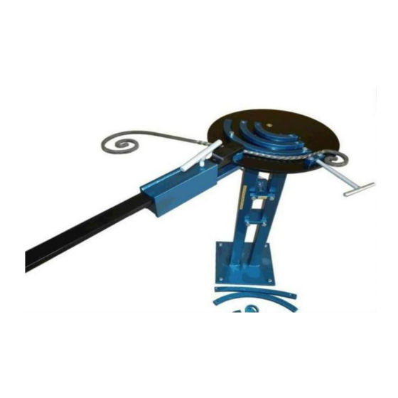
- Page 5 The bender should fasten the bending machine to the pole with two bolts (12x25 to the bottom sub-plate) with the help of two workers. The bender inserts the lever into the 50 mm x 20 mm hole in the bending machine arm. The bender fastens the Ø500 mm bending plate (diameter "d") to the top sub-plate of the bending machine arm with two hexagon-socket cap screws - 12 to be fastened from the top side.
- Page 6 6. After the work is completed. Once the work is completed, protect the bending machine from tipping over. Secure the bending machine arm and the bending lever with a set screw. Place the blocks, arches, clamp, bolts and rolls on the bottom plate of the bending machine pole (the bottom plate is fastened to the floor with screws).
Need help?
Do you have a question about the GS-R and is the answer not in the manual?
Questions and answers