Advertisement
Quick Links
Advertisement

Summary of Contents for OwnElement NorticDesk Pro Series
- Page 1 Pro Series Frame Assembly Instructions...
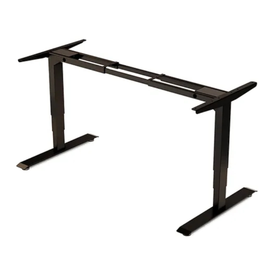
- Page 3 Lets set up your new standing desk.
-
Page 4: Table Of Contents
Contents Cautions and Use In the Box Specs Quick Look Assembly Troubleshooting Anti-Collision... -
Page 5: Cautions And Use
Cautions Please read this manual carefully. If the desk changes hands, please provide this manual to the new owner. Make sure the desk top is not touching any obstacles or walls. Make sure all cords (monitors, speakers or any item on the desk) are of appropriate length to accommodate full range of height adjustment. -
Page 6: In The Box
In the Box Hex Wrench Phillips Head Screw Driver Frame End w/ Control Lifting Column x2 Foot x2 Frame End Box Bracket Side Bracket x2 Control Box Center Rail x2 Leg Extension Cable Memory/Simple Levelling Studs x4 Cable Clip x5 Handset Power Cable Small (M6x12) -
Page 7: Specs
Specs Pro Extended Height Range 70cm (27.5”) – 115cm (45.2”) 60cm (23.6”) – 125cm (49.2”) (without desk top) Travel Speed 30mm/s 38mm/s Operating Noise Less than 50dB Less than 50dB Load Capacity 100kg (220lbs) 100kg (220lbs) Other Features Anti-Collision, Smooth Anti-Collision, Smooth Start/Stop Start/Stop... -
Page 8: Assembly
Assembly STEP 1 Lifting Column Frame End Small Machine Screw x4 Take the top frame apart by separating the Frame Ends and the Center Rails. Insert one of the Lifting Column (either one, they’re the same) into one of the Frame End (also the same) as shown. - Page 9 STEP 2 Step 1 Assembly Side Bracket Flat Head Washer x10 Machine Screw x4 Align the two holes of the Side Bracket with the Frame End Screw of the Step 1 Assembly. Thread two Machine Screws through, once both the screws are in place, tighten them completely.
- Page 10 STEP 4 Foot Medium Levelling Stud x4 Machine Screw x8 Loosely attach a Foot to the bottom of each Lifting Column, using four (4) Medium Machine Screws per Foot. Once all the screws are in place, tighten them down all the way in an X pattern.
- Page 11 STEP 6 Long Medium Wood Screw x10 Machine Screw x10 Double check to make sure the base is properly centered, and the pre-drilled holes in the desk top (if there are any) are aligned with the holes in the frame. If the pre-drilled holes have metal inserts, you will need to use the Machine Screws.
- Page 12 STEP 7 Headless Machine Screw x8 Slide the Center Rails to the center and insert Headless Machine Screws partially (Four (4) screws on either side). Once all of the screws are in place, and the center rails are adjusted, tighten the screws all the way to lock the Center Rails down firmly.
- Page 13 STEP 8 Handset Small Wood Screw x2 If you haven’t already, now is a good time to decide which side you want your Handset to be on. If you have an Own Element desk top, there will be pre-drilled holes for attaching your Handset along the front of the desk top.
- Page 14 STEP 9 Control Box Leg Extension Cable Cable Clip x5 Power Cable Slide the Control Box onto the Frame End with the receiving bracket. Once the Control Box is securely in place, it’s time to attach the rest of the cables. Power Lifting Columns Handset...
- Page 15 Great! You’re almost there. A few final steps The Flip Turn the assembled desk right-side-up. You might need two people for this task. Be careful not to put weight on the Handset while turning the table. If the surface is not levelled (maybe you’re placing your desk on a rug), adjust the Levelling Studs as needed.
-
Page 16: Troubleshooting
Troubleshooting If you see an error message (E11 – E21) or if your desk is not functioning as intended, confirm all your cables are correctly connected. Once you have checked that all connections are secure, re-calibrate your desk following the calibration steps. If you see the error message E08, your desk might not be properly levelled. - Page 17 All this information can be found online at ownelement.com/instructions...
Need help?
Do you have a question about the NorticDesk Pro Series and is the answer not in the manual?
Questions and answers