Table of Contents
Advertisement
Quick Links
Advertisement
Table of Contents

Summary of Contents for Liberate Medical VentFree
- Page 1 Document #: Version MAN-006 Document Title: VentFree User’s Manual EUA Approval Date: Effective Date: 28-Apr-2020 28-Apr-2020 CHANGE SUMMARY Rev # Date Description EUA requirements 21-Apr-2020 CO-2020-348 Liberate Medical Electrodes 28-Apr-2020 CO-2020-382...
- Page 2 VentFree has been authorized by FDA under an Emergency Use Authorization (EUA). VentFree is authorized only for the duration of the declaration that circumstances exist justifying the authorization of the emergency use under section 564(b)(1) of the Act, 21 U.S.C. § 360bbb-3(b)(1), unless the authorization is terminated or revoked sooner.
-
Page 3: Table Of Contents
Product Description Principles of Operation VentFree Features VentFree Indications for Use VentFree Contraindications VentFree Warnings VentFree Dangers Cautions Electrode Cautions Flow Sensor Cautions 1.10 Stimulator Adverse Effects 1.11 Glossary of Symbols VentFree Directions for Use Getting Started External Power Electrode Setup... - Page 4 5.8.2 Flow Sensor 5.8.3External AC/DC Converter Environmental Conditions 5.10 EN 60601-1 Classification 5.11 Electromagnetic Compatibility (EMC) Tables Disinfection and Cleaning Agents VentFree and AC/DC Converter Cleaning and Disinfection Methods DOCUMENT: MAN-006-01 Effective: 28-Apr-2020 CONTROL NUMBER: CO-2020-382 Page 4 of 69...
- Page 5 Electrodes Cleaning and Disinfection Methods Cleaning and Disinfection of the Flow Sensor Battery Replacement Battery Disposal Calibration and Maintenance Repairable Parts Equipment Disposal Manufacturer Information DOCUMENT: MAN-006-01 Effective: 28-Apr-2020 CONTROL NUMBER: CO-2020-382 Page 5 of 69...
-
Page 6: Product Description
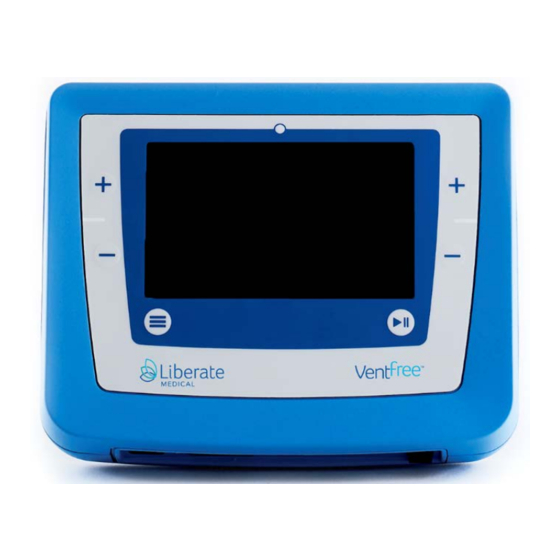
Product Description Figure 1: VentFree VentFree is an electrotherapy device that monitors the patient’s breathing activity using an airflow sensor, and during the expiratory phase of breathing, applies transcutaneous neuromuscular electrical stimulation (NMES) to the abdominal wall muscles over two stimulation channels. -
Page 7: Ventfree Features
An important advantage of using NMES in critically ill respiratory patients is that it can be used to recruit the abdominal wall muscles in the absence of patients’ voluntary or automatic recruitment of those muscles. VentFree Features • Does not depend on patient participation. • Non-invasive NMES. -
Page 8: Ventfree Indications For Use
The VentFree muscle stimulator is intended to be used by healthcare professions in a healthcare facility. It is recommended to be used for two 30 minute sessions per day (one in the morning and one in the afternoon / evening), five days per week, for six weeks or until successful weaning, whichever occurs sooner. -
Page 9: Ventfree Contraindications
VentFree Contraindications VentFree should NOT be used for the following situations or patients with: ● Do not use with demand type implanted pacemaker or defibrillator. ● Do not use electrical stimulation over pregnant uterus. ● Do not use on a patient with recent abdominal surgery with open abdominal wounds. - Page 10 Defibrillation Signals – In certain circumstances, there can be risk of burns under the electrode sites during the defibrillation. Safety – The safety and efficacy of the VentFree system depends on the proper use and handling of the device and accessories. If used improperly, VentFree has a potentially hazardous electrical output.
-
Page 11: Ventfree Dangers
Neurally Adjusted Ventilatory Assist (NAVA) Ventilation - Do not use device if in conjunction with NAVA ventilation mode VentFree Dangers Dangerous voltage – Stimulus delivered by VentFree, in certain configurations, may deliver a voltage of up to 100 Volts per pulse. Biohazardous materials – Handle, clean and dispose of components and accessories that have encountered bodily fluids according to National, Local and Facility rules, regulations and procedures. - Page 12 Sedated Patients – Clinician’s discretion should be used when setting stimulation levels on sedated patients or on skin areas with reduced sensation. Colostomy – Patients with a colostomy should be closely monitored while using VentFree. Heart Problems – Use caution for patients with suspected or diagnosed heart problems.
-
Page 13: Electrode Cautions
Body Mass Index (BMI)- VentFree may not be effective on patients with a BMI over 35. External AC/DC Converter – Use only the VentFree external AC/DC converter approved by Liberate Medical, LLC. -
Page 14: Stimulator Adverse Effects
● If the Flow Sensor becomes dirty, it can be washed with soap and water and then properly disinfected unless the facility’s IC procedures indicate that the disposable be discarded. ● Do not alter the Flow Sensor tubing. ● Follow Instructions for use provided with the Flow Sensor. 1.10 Stimulator Adverse Effects •... -
Page 15: Glossary Of Symbols
100 Volts per pulse. Indicates the need for the user to consult the User’s Manual for important cautionary information such as warnings and precautions that cannot, for a variety of reasons, be presented on VentFree itself. - Page 16 Indicates the identification number of manufacturing batch or lot. Indicates the expiration or use by date of the accessories. Indicates that VentFree or its accessories have not been subject to a sterilization process. Indicates the degree of protection provided by the enclosure. VentFree is protected against solid IP22 foreign objects of 12.5mm or greater (similar to fingers) and against the effects of...
-
Page 17: Ventfree Directions For Use
Figure 3: VentFree Components External Power VentFree can be battery operated or connected to an external source of power (as shown in Figure 3). When connected to the external AC/DC converter, the battery will also be charged. Do not use VentFree if external AC/DC converter enclosure is damaged. -
Page 18: Electrode Setup
ALWAYS use the AC/DC converter with the corresponding regional AC Inlet plug. Electrode Setup 1. The unit must be turned off and electrodes disconnected from VentFree before and after each treatment or as directed by prescribing physician. DOCUMENT: MAN-006-01 Effective: 28-Apr-2020... - Page 19 2. Clean electrode application area with soap and water or as directed by prescribing physician. Rinse and dry. Electrodes should only be applied to intact, clean skin (e.g., not over open wounds, lesions, infected, or inflamed areas). It is recommended that patients with excessive body hair be shaved prior to applying electrodes.
- Page 20 Figure 4. Optimal Electrode Placement DOCUMENT: MAN-006-01 Effective: 28-Apr-2020 CONTROL NUMBER: CO-2020-382 Page 20 of 69...
-
Page 21: Electrode Cautions
Electrode Cautions DO NOT place electrodes on broken skin. If skin irritation develops, discontinue use. Consult prescribing physician. Replace electrodes when they do not adhere or treatment becomes uncomfortable. For single patient use only. However, the electrodes may be repositioned several times on the same patient. Keep electrodes separated during treatment. -
Page 22: Electrode Warnings
Using stimulation electrodes that are too small or incorrectly applied could result in discomfort or skin burns. DO NOT cut electrodes other than as indicated by the dotted lines in the back of the electrodes. Electrode Warnings Stimulation should not be applied transcerebrally or over the anterior neck region. -
Page 23: Re-Application And Storage Of Electrodes
Do not apply electrical stimulation transthoracically (through the chest area) as the introduction of electrical current into the heart may cause cardiac arrhythmias. Other Electrode Placement - Stimulation should not be applied across or through the head, directly on the eyes, covering the mouth, on the front of the neck (especially the carotid sinus), or placed on the chest and the upper back or crossing over the heart. -
Page 24: User Interface
PATIENT ONLY. User Interface The user interface of VentFree utilizes a 6-button interface on the device. The available functions include a “PLAY/PAUSE” button with “+” (increment Parameter) and “-” (decrement Parameter) buttons on either side of the LCD screen as well as a MAIN MENU button. In addition to the six user buttons there is a Stimulation LED Indicator light at the top of the screen. -
Page 25: Connections
Connections The bottom side of VentFree contains several connection ports along with the power switch as shown in Figure 4. The Flow Sensor Port has a custom connection to the Flow Sensor tubing. The electrode port connects to the lead cable from the electrodes. -
Page 26: Connecting The System
Connecting the System 1. The device should be disinfected before use. Before setting up VentFree, verify that the power switch is in the “off” position (refer to Figure 5). OFF Position top portion of the switch is pressed in. Figure 6: Power Switch OFF Position 2. - Page 27 3. Insert the Flow Sensor between the patient’s endotracheal tube and Wye joint, making sure that the blue tube on the flow sensor is proximal to the patient. The patient setup is shown below in Figure 7. If the sensor was installed from a prior treatment, remove and discard the caps.
- Page 28 4. The stimulation electrodes should be positioned over the posterolateral side of the abdominal wall, so that the transverse abdominal, internal oblique, and external oblique muscles will be stimulated. The placement of the stimulation electrodes is illustrated in Figure 8. This configuration has been demonstrated to be the most effective method of generating abdominal muscle contraction compared with alternative configurations.
- Page 29 5. Plug the electrode cable header into VentFree as shown in Figure 9. Electrodes connection port Figure 10: Electrodes Connection Port NOTE: The Flow Sensor is equipped with a radio-frequency identification (RFID) tag that logs expiration dates and number of uses.
-
Page 30: Setting Up The System
3 Setting up the System 1. If not done before, using the mounting fixture on the back panel, mount VentFree on a dedicated pole as shown in Figure 10. Consult with Liberate Medical, LLC regarding alternative mounting options. Figure 11: VentFree Mounting WARNING: to prevent the accidental ingress of fluids, ALWAYS use VentFree in a vertical position as shown above. - Page 31 Figure 12 Power Switch ON Position 3. Following power up, the device will display a screen for the User to verify he/she has read the warnings, cautions and contraindications of VentFree before use. Upon completion, press CONTINUE. Figure 13 User Verification of reading warnings, cautions and...
- Page 32 Figure 14 : Logo screen Figure 15: Connections screen DOCUMENT: MAN-006-01 Effective: 28-Apr-2020 CONTROL NUMBER: CO-2020-382 Page 32 of 69...
- Page 33 Figure 16: Connections Screen (Expired Disposables) 5. After the LOGO screen is pressed, the CONNECTIONS screen will appear (Figure 13). The CONNECTIONS screen will verify that the Flow Sensor and electrodes are properly connected and not expired (refer to Figure 15 for screen with expired disposables). The CONNECTIONS screen will also inform the user if the battery has enough charge to complete a treatment session.
- Page 34 Figure 18: Manual stimulation screen 2 Figure 19: Manual stimulation screen 3 6. After the setup is confirmed with the CONNECTIONS screen, the MANUAL STIMULATION screen (Figure 16, Figure 17, Figure 18) will display. The setup is intended to adjust stimulation levels to the point where visible and comfortable muscle contractions are observed.
- Page 35 7. Stimulation levels can be adjusted on each channel by pressing the corresponding +/- buttons on either side of the screen. VentFree will output stimulation anytime the “PLAY/PAUSE” button is pressed. Stimulation will cease when the button is released. Refer to the Stimulation Levels section for further details on adjusting levels.
-
Page 36: Stimulation Levels
(internal oblique, external oblique and transverse abdominis). WARNING: If there is no contraction at the maximum stimulation level which does not result in patient discomfort, then the patient is not suitable for therapy with the VentFree device. WARNING: If there is patient discomfort prior to achieving a strong visible or palpable contraction, then the patient is not suitable for therapy with the VentFree device. -
Page 37: Begin Treatment
1. To begin a treatment session, select “BEGIN TREATMENT” on the MANUAL STIMULATION screen. 2. VentFree is now set up in automated mode to apply stimulation in synchrony with exhalation. Figure 19 shows the information displayed while in automated mode. -
Page 38: Treatment Pause
Treatment Pause 1. To pause the treatment session, press the PLAY/PAUSE button. The screen will display the information shown in Figure 20. Figure 21:Paused Treatment 2. To restart the treatment, press the PLAY/PAUSE button. 3. If treatment is to be stopped or discontinued, press the END button. Treatment Discontinuation 1. -
Page 39: Power Removal And Device Disconnection
Power Removal and Device Disconnection 1. Press FINISH on the END OF TREATMENT screen. 2. Power down VentFree by pressing the top portion of the Power Switch. 3. Disconnect the electrodes and Flow Sensor from VentFree. 4. Carefully remove the electrodes from the patient. -
Page 40: Main Menu
o ALWAYS USE NEW CAPS TO CAP THE FLOW SENSOR TUBING 7. The device and all accessories should be cleaned after use by wiping surfaces down with disinfectant. Refer to the Disinfection and Cleaning Section 6 for further instructions. MAIN MENU Figure 23 MAIN MENU 3.6.1 Brightness... -
Page 41: Key Volume
Figure 25:Key Volume 3.6.3 Session Length The SESSION LENGTH is adjustable on VentFree. Once on the screen, the “+/-“ buttons, on either side of the screen, can be pressed to adjust the session length between 5 and 60 minutes. Figure 26:Session Length... -
Page 42: Date/Time Menu
3.6.4 Date/time menu The DATE/TIME menu available on VentFree is used to adjust the current date and time on the device. Figure 27 Date/time menu 3.6.5 Stim Settings Reserved for Factory Settings. 3.6.6 About Information about VentFree can be found on the ABOUT screen which can be accessed through the MAIN MENU. -
Page 43: Error Messages And Troubleshooting
4 Error Messages and Troubleshooting REASON MESSAGE Low battery CAUTION: Battery will run out before session end! No battery CAUTION: No battery detected! Reversed Flow Sensor CAUTION: Reversed Flow Sensor detected Reverse Flow Sensor connection. Low flow CAUTION: Low flow detected! Check Flow Sensor and connection to patient. No Flow CAUTION: No flow detected! Check Flow Sensor and connection to patient. -
Page 44: Technical Data
● Capacity: 6.4 Ah (48 Wh) ● Approvals: CE, FCC, UR The Battery is part of VentFree. ONLY Batteries supplied by Liberate Medical, LLC shall be used. 5.1.2 AC/DC Converter (Power Supply) ● Input: 100 ~ 240 VAC, 50 ~ 60 Hz ●... -
Page 45: Standard Measurement Conditions
● Load: 1000 ohm ● AC/DC converter 9V DC +/- 10% 5.3 Outputs The VentFree muscle stimulator provides current controlled biphasic symmetrical rectangular pulses. An example waveform in shown in Figure 29. The device has the following stimulation output ranges: •... -
Page 46: Typical Waveforms
Figure 29 Stimulation output 100 mA 700 us interphase, 400 us Pulse Width, 50Hz Frequency 5.4 Typical Waveforms The following are typical waveforms as measured through a 100 ohm current sense resistor while providing maximum stimulation to purely resistive loads of 1000 ohm and 500 ohm. Figure 30: Stimulation output 100 mA 700 us interphase, 400 us Pulse Width, 50Hz Frequency DOCUMENT: MAN-006-01 Effective: 28-Apr-2020... -
Page 47: Treatment Duration
Active stimulation output from the device is indicated by a yellow LED above the touchscreen and by a green line under the flow signal depiction on VentFree’s screen. Stimulation Level of each channel is indicated with numerical characters showing the circulating current intensity with 20% Accuracy and Precision levels. -
Page 48: Electrodes
● There are 3 size options for the VentFree electrodes. ● To decrease electrodes size, tear the electrodes at the desired dashed line shown in the top of Figure 33. ● Part Number: Electrodes patches are part of the VentFree Accessory Kit Assembly, DOCUMENT: MAN-006-01 Effective: 28-Apr-2020... -
Page 49: Flow Sensor
PN: LIB-VF-0070 and are not sold individually by Liberate Medical, LLC 5.8.2 Flow Sensor Figure VentFree Flow Sensor Part Number: The flow sensor is part of the VentFree Accessory Kit Assembly, PN: LIB-VF- 0070 and are not sold individually by Liberate Medical, LLC DOCUMENT: MAN-006-01 Effective: 28-Apr-2020... -
Page 50: 3External Ac/Dc Converter
5.8.3External AC/DC Converter Figure 34. External AC/DC Converter Reorder Number: LIB-VF-307 / Part Number: MEANWELL 60109-LI Environmental Conditions ● Operational Temperature: 41 °F and 95 °F (5 °C and 35 °C) ● Humidity (Maximum): 10% to 95% RH ● Atmospheric Pressure: 70 kPa to 106 kPa (10.2 psia to 15.4 psia) ●... -
Page 51: Electromagnetic Compatibility (Emc) Tables
Guidance and Manufacturer’s declaration – electromagnetic emissions NOTE: The EMISSIONS characteristics of VentFree make it suitable for use in industrial areas and hospitals (CISPR 11 class A). If it is used in a residential environment (for which CISPR 11 class B is normally required) this equipment might not offer adequate protection to radio-frequency communication services. - Page 52 Immunity Test IEC 60601 Test Compliance Electromagnetic Environment – Guidance Level Level ±8kV Contact ±8kV Contact Floors should be wood, concrete or ceramic tile. If floors are synthetic, the r/h IEC 61000-4-2 ± 2 kV, ± 4 kV, ± 8 ±...
- Page 53 DOCUMENT: MAN-006-01 Effective: 28-Apr-2020 CONTROL NUMBER: CO-2020-382 Page 53 of 69...
- Page 54 Recommended Separation Distances between Portable and Mobile RF Communications Equipment and VentFree The VentFree device is intended for use in an electromagnetic environment in which radiated RF disturbances are controlled. The customer or the user of the VentFree device can help prevent...
-
Page 55: Disinfection And Cleaning
2. Remove all connections from VentFree. 3. Keep VentFree always in the vertical upright position. 4. Using any of the wipes listed above, wipe every surface of VentFree and the External AC/DC Converter to remove any visible signs of soil or body fluids. - Page 56 DOCUMENT: MAN-006-01 Effective: 28-Apr-2020 CONTROL NUMBER: CO-2020-382 Page 56 of 69...
- Page 57 Electrodes Cleaning and Disinfection Methods Before and After each use, VentFree shall be cleaned and disinfected. Following are instructions for cleaning electrodes After treatment: 1. Turn VentFree off. 2. Disconnect the Electrodes from the patient and VentFree, if not done before.
- Page 58 ALWAYS follow the institution Infection Control procedures regarding any logging of equipment disinfection. Electrodes are SINGLE PATIENT USE ONLY DOCUMENT: MAN-006-01 Effective: 28-Apr-2020 CONTROL NUMBER: CO-2020-382 Page 58 of 69...
- Page 59 PRIOR TO THE NEXT USE o ALWAYS USE NEW CAPS TO CAP THE FLOW SENSOR TUBING 3. Turn VentFree off. 4. Using any of the wipes listed above, wipe the external surface of the Flow Sensor, its tubing and connector to remove any visible signs of soil or body fluids.
- Page 60 ONLY USE approved cleaning agents ALWAYS follow the institution Infection Control procedures regarding the use of Personal Protective Equipment when handling cleaning and disinfection agents ALWAYS follow the institution Infection Control procedures regarding any logging of equipment disinfection. The Flow Sensor assembly SINGLE PATIENT USE ONLY If visible signs of body fluids are observed inside the Flow Sensor, rinse with sterile water and air dry DOCUMENT: MAN-006-01...
- Page 61 DOCUMENT: MAN-006-01 Effective: 28-Apr-2020 CONTROL NUMBER: CO-2020-382 Page 61 of 69...
- Page 62 VentFree charging cable. Stimulation can be provided while the device is connected to the power main. If the battery in VentFree is no longer holding a charge long enough for a stimulation session or is not charging, the battery needs to be replaced. Only batteries supplied by Liberate Medical, LLC should be used in VentFree.
- Page 63 2. Turn off the device by pressing the top portion of the power switch (Figure 36). Press to turn the device OFF. 3. Disconnect VentFree from the external AC/DC converter. 4. Disconnect the Electrodes Leads and Flow Sensor. DOCUMENT: MAN-006-01...
- Page 64 Figure 36: VentFree with screws removed 5. Place VentFree facing down and unscrew each corner screw of the device ( Figure 37). DOCUMENT: MAN-006-01 Effective: 28-Apr-2020 CONTROL NUMBER: CO-2020-382 Page 64 of 69...
- Page 65 Figure VentFree with back panel removed 6. Remove the back panel (Figure 38). Figure 38: VentFree battery with pull tab 7. Remove the current battery by gently lifting it vertically from the device using the battery’s pull tab (Figure 39).
- Page 66 Figure 39 : VentFree battery packaging 8. Remove the new battery from its packaging (Figure 40). Figure 40: VentFree battery replaced DOCUMENT: MAN-006-01 Effective: 28-Apr-2020 CONTROL NUMBER: CO-2020-382 Page 66 of 69...
- Page 67 Figure 41: VentFree battery seated 9. Place the new battery in VentFree. The battery should slide vertically over the connector (Figure 41). Make sure the battery is seated into the battery compartment (Figure 42). Figure 42: VentFree back panel and screws replaced 10.
- Page 68 5 years from the manufacturing date. 8.1 Repairable Parts VentFree does not have repairable parts. In the event of any malfunction other than those requiring a change of battery or accessories, contact Liberate Medical, LLC.
- Page 69 6400 Westwind Way, Suite A Crestwood, KY 40014 1-800-683-5526 DOCUMENT: MAN-006-01 Effective: 28-Apr-2020 CONTROL NUMBER: CO-2020-382 Page 69 of 69...
Need help?
Do you have a question about the VentFree and is the answer not in the manual?
Questions and answers