
Summary of Contents for Shengyi CMT03P
- Page 1 CMT03P Technical Instruction (English Version) Product Name: Mid Motor Drive Unit Product Model: CMT03P (Standard Configuration) ~ - 1 - ~...
-
Page 2: Important Notice
Important Notice •Please read this manual and the attached installation manual carefully. If you are not clear about any part of the information in this manual, please do not install it. Please consult the sales office. •Please contact the dealer for product information not described in this manual. •... - Page 3 Catalogue 1. Mid motor 2. Attachment 3. Assembly method 4. Matters needing attention and fault analysis 5. Packing list 6. Packaging method ~ - 3 - ~...
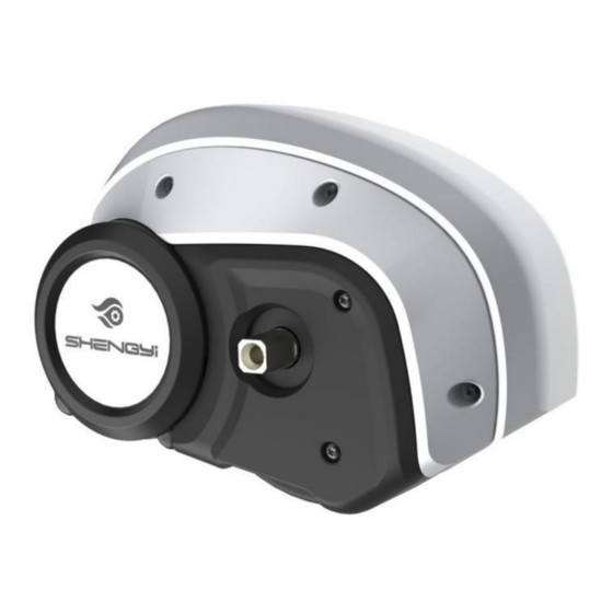
- Page 4 1. Mid motor drive unit ★ It can meet the needs of bicycle installation and is convenient to install; The central drive unit has a high degree of modular design, which is ★ convenient for motor maintenance; ★ The middle drive unit adopts half-package design, which is convenient for customers to customize;...
-
Page 5: Main Technical Parameters
1.2 Main technical parameters Model CMT03P36 CMT03P48 Rated power 350W@105RPM 450W@105RPM Maximum input 500W(T<7min); max: 650W(T<7min); max: power 640W 860W Rated voltage Maximum current limit Maximum torque 120Nm@25RPM 120Nm@25RPM Maximum speed 115RPM 115RPM Maximum efficiency ≥80% ≥80% 2. Attachment 2.1 Instrument 2.1.1 Instrument name Medium color TFT LCD instrument, model: APT 850C LCD display description and key function description... - Page 6 2.1.2 Parameter setting See 850C-ENS product specification -J-202106 billion. 2.2 Speed sensor 2.2.1 Product model Model: SPL-10 2.2.2 Appearance 2.2.3 Product installation drawing ~ - 6 - ~...
- Page 7 Locking Torque (<1Nm) 2.2.4 Specific specifications Parameter Numerical value Rated voltage DC5V Rated current Pulse/cycle Installation distance 3-10mm Working temperature -30~70℃ Waterproof grade IPX7 Authentication CE ROHS 2.3 Dental tray 2.3.1 Appearance of dental tray: (as shown in the figure) 2.3.2 Tooth plate model: 42T unilateral chain cover 2.3.3 Basic parameters of dental tray Number of teeth: 42 teeth...
-
Page 8: Other Accessories
2.4 Crank 2.4.1 Appearance of crank: (as shown in the figure) 2.4.2 Crank model: TS1-170AA 2.4.3 Basic parameters of crank: Length: 170mm Material: 6061 Color: black * Note: The left and right cranks have different thread directions, and the left crank is marked with "L"... - Page 9 3. Assembly method 3.1 System schematic diagram and wiring diagram ~ - 9 - ~...
-
Page 10: System Schematic Diagram
3.1.1 System schematic diagram ~ - 10 - ~... -
Page 11: System Wiring Diagram
3.1.2 System wiring diagram ~ - 11 - ~... -
Page 12: Install The Motor
3.2 Schematic diagram of loading 3.2.1 Threading Penetrating the external speed sensing adapter, headlight adapter, instrument adapter, rear light adapter and power adapter into the whole vehicle according to the requirements of the whole vehicle; Insert the above wires into the motor according to 3.1.2 System Wiring Diagram; Arrange the line length and position;... - Page 13 3.2.3 Install the plastic housing. Fix the plastic shell to the motor; Lock six M4X8 hexagon socket head screws as shown in the figure(locking torque: <1Nm); ① ② ③ 3.2.4 Install the tooth plate and lock the screw of the tooth plate. Install the tooth disk assembly on the motor according to the spline groove direction;...
- Page 14 3.2.5 Install left and right cranks and lock crank screws. Sleeve the crank on the central shaft (the included angle between the left and right cranks is 180)(locking torque 30-35Nm); Lock the crank screw as shown in the figure; 3.2.6 Install external speed sensor and magnetic steel. See 2.2.3 Product Installation Diagram for installation requirements.
- Page 15 4. Matters needing attention and fault analysis 4.1 Matters needing attention It should be parked in a ventilated and dry warehouse. It should not be parked in a damp, acid and alkali place, nor should it coexist with magnetic articles. Each connector is plugged into place according to the arrow;...
- Page 16 Note: When the motor works without external force, it is normal for the crank to follow. 4.3 Other fault analysis and error codes error Wrong definition LED flashing describe code 0x00 normal Flash once per second 0x10 overtension Flash once restorability 0x11 undervoltage...
-
Page 17: Packing List
error Wrong definition LED flashing describe code beyond 0x23 Phase line fault Flash 7 times retrieve 0x24 Hall fault Flash 5 times restorability 0x25 Brake failure restorability note: Recoverable-after the alarm, the EPAC drive system will detect it in real time. After the fault disappears, the alarm will be relieved and normal operation will be achieved. - Page 18 17. 1 power adapter cable 6. Packaging method Wrap the motors in plastic film bags, and put 3 sets in one box; Accessories are packaged separately from the motor; (Pay attention to counting quantity); * In addition, the connecting frame is shipped separately in advance, which is convenient for welding the frame in advance and facilitating production arrangement.
Need help?
Do you have a question about the CMT03P and is the answer not in the manual?
Questions and answers