Table of Contents
Advertisement
Quick Links
Advertisement
Table of Contents

Summary of Contents for INFITHEON infiSENSIS
- Page 1 Autonomous Alarm System User Manual V2.0 © INFITHEON Technologies...
-
Page 2: Table Of Contents
Features System Basics 1.4.1 Anti-Burglary Protection 1.4.2 High Temperature Protection 1.4.3 Alarms 1.4.4 Tele-Control System Components USER INTERFACE infiSENSIS Device LCD Front Panel Keypad 2.3.1 Status LEDs 2.3.2 Alphanumeric Keypad 2.3.3 Navigation Keys 2.3.4 Function Keys Alarm Siren Switches / Interface Panel 2.5.1... - Page 3 GSM Call ON 3.10 SMS ON 3.11 RELAY ON 3.12 Default Values BASIC SYSTEM OPERATIONS System Initialisation 4.1.1 System Calibration 4.1.2 GSM Operation Setup 4.1.3 Other parameters setup Arming/Disarming the System Generating Emergency User Alarms ADVANCED SYSTEM OPERATIONS © INFITHEON Technologies...
- Page 4 Using Profiles Tele-Control Software Upgrade SYSTEM TESTS Infrasonic Sensor Test Digital Input Test Relay Test Light Sensor Test Status SMS Test APPENDIX A DEFAULT VALUES APPENDIX B Table of LED Indications APPENDIX C SMS Table APPENDIX D Tele-Control © INFITHEON Technologies...
-
Page 5: System Overview
The system consists of one single device (a mini-computer with sensors) housed within a plastic panel enclosure. It requires no special installation. It is very easy to operate the infiSENSIS unit in your house, office or any other enclosed space. You only need to plug it to the mains (a power supply unit is included), and then activate it. -
Page 6: Applications
InfiSENSIS can be remotely operated through SMS’s or unanswered calls. Features InfiSENSIS alarm system has many features in order to suit a wide range of applications. This manual outlines all of those features in detail. If you have any questions regarding the features described in this manual, please ask your local provider. -
Page 7: System Basics
Light Sensor Easy to use keypad and LCD display Input for external sensors. InfiSENSIS can be connected through this input to a plethora of commercial sensors, such as infrared radars electromagnetic traps, motion detectors etc. Relay output (NO/NC) for the remote control & operation of lights and home appliances ... -
Page 8: High Temperature Protection
1.4.3 Alarms In the case of an intrusion attempt infiSENSIS will alert you with an audio alarm (the embedded loud siren of the system will sound) and an alarm message will also be sent to the predefined mobile numbers. -
Page 9: Tele-Control
The System offers a wide range of Tele-control functions which provide remote access to it, via a mobile phone. You can call your home at any time in order to operate your infiSENSIS or to check the status of your system while you are away. -
Page 10: User Interface
Device InfiSENSIS provides you with all the functions you need to control your system and it consists of the following components: ... -
Page 11: Lcd Front Panel
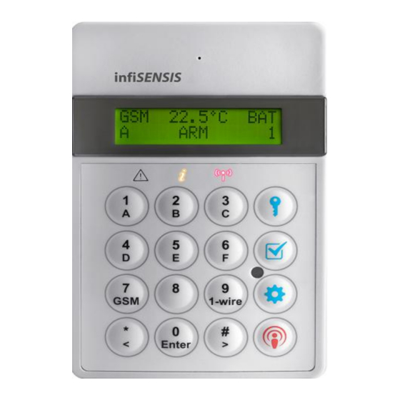
The LCD Front Panel consists of 2 lines, 16 characters each and displays various messages. Keypad The keypad of your system consists of 3 Status LEDs (Event, Information and GSM), 10 Alphanumeric Keys, 4 Function Keys and 3 Navigations Keys. © INFITHEON Technologies... -
Page 12: Status Leds
Figure 1. Keypad 2.3.1 Status LEDs The Status LEDs inform you about the system status, power failures, or system trouble conditions. There are three LEDS: © INFITHEON Technologies... -
Page 13: Alphanumeric Keypad
SIM card (or) the SIM card is not valid (or) the PIN code has not been de-activated. 2.3.2 Alphanumeric Keypad The alphanumeric keypad consists of 10 keys and enables you to enter the GSM numbers and other arithmetic characters required by your device. 2.3.3 Navigation Keys The last three keys in the Keypad © INFITHEON Technologies... -
Page 14: Function Keys
2.3.4 Function Keys The four function keys allow you to perform very easily and quickly certain functions of the system. Specifically, the 4 functions keys are the following: ARM/DISARM the System TEST MENU SETUP MENU © INFITHEON Technologies... -
Page 15: Alarm Siren
Switches / Interface Panel The Switch / Interface Panel is located in the bottom side of the device and consists of: ON/OFF Switch Mini USB Interface SIM Card Holder Case External Device Interface. © INFITHEON Technologies... - Page 16 Pin 2: Relay position Pin 3: Digital Input (DIN) Pin 4: Ground Pin 5: 1-Wire I/O – 3.3V DC (1-wire protocol is not supported) Pin 6: 3.3V or 12 V DC (Section 3.6 ΕΧΤ Sensors Powering) Pin 7: RS232 RX © INFITHEON Technologies...
-
Page 17: On/Off Switch
Manual). Once the PIN protection is removed your card is ready to be used with infiSENSIS. InfiSENSIS will be able to send you SMS messages, in the case of an event, only when you insert a valid SIM card. © INFITHEON Technologies... - Page 18 In the External Device Interface (I/O) connector you can connect various peripherals, such as an External Siren, Infrared Sensor, thermostat, electromagnetic sensors, etc. (see Figure 2. Switch/Interface Panel). The pin-out of the connector can be found in Table 1. Pin configuration of the External Device Interface Connector. © INFITHEON Technologies...
-
Page 19: System Setup
The parameter values depend on the particular conditions of the protected spaces. Inappropriate parameter value setting could result in ‘false alarms.’ In order to calibrate the infrasonic sensors you can adjust the following two parameters: Sensitivity Hardness © INFITHEON Technologies... -
Page 20: A) Sensitivity Calibration
“Sensitivity: Χ (1- 16) is displayed and underneath it shows the corresponding bars. Press to increase the sensitivity up to 16 bars (if you wish to decrease the sensitivity, press Press to select the desired sensitivity level. The default value is 4 (bars). © INFITHEON Technologies... -
Page 21: B) Hardness Calibration
. “Hardness / Χ” is shown on the display. 5. Press the key to increase hardness value or the key to decrease the Hardness value to the desired level. When the desired value is shown, press The default value is 2. © INFITHEON Technologies... -
Page 22: Gsm
1. In the main MENU press 2. Press until “Setup Menu / GSM” is displayed. 3. Press . “GSM Setup / GSM Numbers” is displayed. 2. Press . “GSM Number: 1” is displayed. Input the mobile telephone number using the © INFITHEON Technologies... -
Page 23: Incoming Call Visible (Incall Visible)
4. Press . “inCall Visible” is displayed. 5. Press . The message <Incoming Call> is Visible is displayed. Press once more the incoming call numbers will be displayed on the device screen. In case you desire the number © INFITHEON Technologies... -
Page 24: Still Alive
“GSM Setup / Still Alive” is displayed. 5. Press . “Call me back every X min” is displayed. 6. Press the key to increase or the key to decrease the time interval (in minutes). When the desired value is displayed, press © INFITHEON Technologies... -
Page 25: Light Sensor
The default value is 0 minutes, meaning no periodic messages are sent. Light Sensor This feature allows infiSENSIS to detect sudden light changes: To activate the light sensor: 1. In the main MENU press 2. Press until “Light Sensor” is displayed. -
Page 26: Alarm Duration
Alarm Duration respectively. When the desired value is displayed press The default value is 5 seconds. Note that the system automatically re-arms when time exceeds the set Alarm Duration value. © INFITHEON Technologies... -
Page 27: Selection Of External Sensors Voltage (Εχτ Sensors Powering)
1 for 3.3V DC or by the letter H for 12V DC (Section 2.2 LCD Front Panel).Before connecting any external sensors to infiSENSIS please make sure that you have selected the appropriate voltage. -
Page 28: Temperature Trigger
If you set a high trigger (temperature higher than XX.X C) then a trigger is activated when the space temperature becomes higher than the set value. To set a temperature trigger: 1. In the main MENU press © INFITHEON Technologies... -
Page 29: Light Trigger
0% to 100%. To set a light trigger: 1. In the main MENU press 2. Press times until “Setup Menu / Triggers” is displayed. 3. Press and then until “Trigger Setup / Light” is displayed. © INFITHEON Technologies... -
Page 30: Audio Alarm On
Digital Input – DIN Temperature Light. To select one of the above events to set the AUDIO Alarm ON: 1. In the main MENU press 2. Press . “Setup Menu / Audio Alarm on …” is displayed. © INFITHEON Technologies... -
Page 31: Gsm Call On
The events that are monitored and can be selected to give a GSM call of a few seconds duration, as a notification to the user (first number on the list), are the following: Infrasonic Alarm Personal Alarm Digital Input – DIN Temperature © INFITHEON Technologies... -
Page 32: Sms On
The default value is: GSM OFF. 3.10 SMS ON This feature allows you to define the events which will cause the system to send an SMS message to all predefined mobile telephone numbers. SMS will be sent whether the system is © INFITHEON Technologies... - Page 33 5. Press to change the state of the event (e.g. from OFF to ON or from OFF to ON). If you wish to change the state of another event, press until the event you wish to activate is © INFITHEON Technologies...
-
Page 34: Relay On
Personal Alarm Event Digital Input Event Temperature Event Light Event In order to select one of the above events in order to activate the Relay Output, perform the following: 1. In the main MENU press © INFITHEON Technologies... -
Page 35: Default Values
The default values of all the parameters are given in Appendix A. To set the default values perform the following: 1. In the main MENU press 2. Press until “Setup Menu / Default Setup” is displayed. © INFITHEON Technologies... - Page 36 3. Press . “Default Set up / Are you sure?” is displayed. 4. Press to select the default values, or cancel the operation and return to the main MENU. © INFITHEON Technologies...
-
Page 37: Basic System Operations
(doors, windows etc.) and see if the system detects this violation. If the system detects all the violations is ready for operation. If any violation is not detected, then you may change the corresponding parameters (sensitivity and hardness) and © INFITHEON Technologies... -
Page 38: Gsm Operation Setup
(Still Alive). Set all the GSM related parameters (Still Alive, GSM Call ON and SMS ON) to the desired values (Sections 3.2.4, 3.9, 3.10) © INFITHEON Technologies... -
Page 39: Other Parameters Setup
(appropriate profile and parameters setup selected, valid SIM card etc.). You can arm/disarm (activate/deactivate) the system by using your mobile phone or by pressing the corresponding key on your device. © INFITHEON Technologies... -
Page 40: Generating Emergency User Alarms
Note: Always make sure that the system’s SIM Card is able to send an SMS message (Section 3.10) and that you have inserted all the mobile numbers (Section 3.2.2) which are allowed to communicate with infiSENSIS. Generating Emergency User Alarms In case of an emergency (Burglary, Fire, etc) you can manually activate an alarm. -
Page 41: Advanced System Operations
The following functions can be operated remotely: infiSENSIS offers a wide range of Tele-control functions which provide remote access to it via a mobile phone. You can call your home at any time in order to operate your system or check the status of your system while you are away. - Page 42 Select Profile F (send the SMS “PROFILEF”) Acoustic Monitoring of your space: call the system and wait for an answer – after four (4) rings the device microphone are automatically switched ON and you can hear whatever happens in your space. © INFITHEON Technologies...
-
Page 43: Software Upgrade
Software Upgrade Your device can be software upgraded through an embedded boot loader. Notifications for any new software developments will be readily available on the website: www.infisensis.com. For software upgrades please consult your local dealer. © INFITHEON Technologies... -
Page 44: System Tests
The same applies in the case that the system gives false-alarms. You can also terminate it by pressing Note: Upon test completion reset the ‘’Alarm Duration to any value you feel comfortable (from 1 up to 10 minutes duration). © INFITHEON Technologies... -
Page 45: Digital Input Test
1. In the main MENU press 2. Press until ‘Test Menu/Relay’ is displayed 3. Press . “Relay Testing / Relay Open” is displayed and the relay is activated. Pressing the message RELAY Close is displayed. Pressing the message RELAY Open © INFITHEON Technologies... -
Page 46: Light Sensor Test
Intensity: 0% (the location of the Light Sensor is shown in figure 1). Press to terminate the test. Status SMS Test This test allows you to check the status of your system. To perform the test: © INFITHEON Technologies... - Page 47 Menu / Status SMS” is displayed. 3. Press . The device will send you an SMS reporting the state of its parameters. Press to terminate the test. An example of STATUS SMS parameters: infiSENSIS: ARM **STATUS** INFRASONIC: ON Temp: 17. 0 Power: Battery BAT: 89%...
-
Page 48: Appendix Adefault Values
Light: OFF GSM Call On..: OFF Infrasonic: OFF Personal Alarm: OFF Digital Input: OFF Temperature: OFF Light: OFF SMS On...: Infrasonic: OFF Personal Alarm: OFF Digital Input: OFF Temperature: OFF Light: OFF Battery level: OFF Power/Battery: OFF © INFITHEON Technologies... -
Page 49: Appendix B Table Of Led Indications
Non illuminated 10 sec Green illuminated 1 sec Power Supply Problem Non illuminated 10 sec Green illuminated 1 sec GSM Signal Problem Non illuminated 10 sec Red illuminated Alarm Red illuminated System ARM Green illuminated Incoming Call © INFITHEON Technologies... -
Page 50: Sms Table
GSM operates normally Non illuminated 3.5 sec Red illuminated 1 sec GSM Problem Non illuminated 1 sec APPENDIX C SMS Table INFRASONIC ALARM PERSONAL ALARM ARM RECEIVED DISARM RECEIVED RELAYON RECEIVED RELAYOFF RECEIVED PROFILEA RECEIVED PROFILEB RECEIVED © INFITHEON Technologies... - Page 51 PROFILEC RECEIVED DIGITAL INPUT ALARM TEMPERATURE ALARM LIGHT ALARM POWER SUPPLY CONNECTED POWER SUPPLY DISCONNECTED © INFITHEON Technologies...
-
Page 52: Appendix D Tele-Control
APPENDIX D Tele-Control DISARM RELAYON RELAYOFF STATUS PROFILEA PROFILEB PROFILEC PROFILED PROFILEE PROFILEF © INFITHEON Technologies... - Page 53 The packaging is made entirely of recyclable materials, which you may dispose of at local recycling facilities. To help protect the environment, please dispose of the product properly at your local collection points, when it has reached the end of its useful life and not in the household waste. © INFITHEON Technologies...
- Page 54 ANY DIRECT, INDIRECT, SPECIAL OR CONSEQUENTIAL DAMAGES resulting from the usage of infiSENSIS. The product is sold for any legal use and the responsibility of such use rests solely with the purchaser. The product is sold as a deterrent and no guarantee is given on our part that it will perform as expected under all circumstances.
- Page 55 Copyright © 2013 INFITHEON Technologies Ltd. All rights reserved. No part of this document may be reproduced or transmitted in any form or by any means, electronic, mechanical, photocopying, recording, or otherwise, without prior written permission No part of this document may be reproduced or transmitted in any form or by any means, electronic, mechanical, photocopying, recording, or otherwise, without prior written permission.
- Page 56 © INFITHEON Technologies...
Need help?
Do you have a question about the infiSENSIS and is the answer not in the manual?
Questions and answers