Advertisement
Quick Links
Advertisement

Summary of Contents for YoraHome 6550-PRO
- Page 1 YORAHOME CNC LASER ENGRAVING MACHINE 6550-PRO USER MANUAL Version 1.0 • June, 2022...
- Page 2 Purpose This Manual is intended for assembly of the YoraHome 6550-Pro Laser Engraving Machine. Before beginning assembly, we recommend conducting an inventory using the Packing List to ensure all components are present. NOTE - there may be extra hardware included; this is normal, in case items get dropped or lost.
- Page 3 ➔ Read and understand the entire user manual before attempting assembly or operation ➔ Do not use the laser engraver other than its intended use. If used for other purposes, YoraHome disclaims any real or implied warranty and holds itself harmless from any injury that may result from that use.
- Page 4 Safety ➔ Never leave the laser engraving machine running unattended. Turn the power off and do not leave the machine until it comes to a complete stop. ➔ Keep a fire extinguisher nearby since use of the laser may lead to an unexpected fire. ➔...
- Page 5 6550-Pro is equipped with an Emergency Stop button on top of the Controller. When pressed, this button will latch in the Stop position. To reset, twist the red knob...
- Page 6 Contents Part 1: Packing List Part 2: Mechanical Installation Part 3: Software Introduction Part 4: FAQ...
- Page 7 Part 1 Packing List Name Model Parameter Quantity Picture Front Frame Rail Rear Frame Rail Left Frame Rail Aluminium Profile Right Frame Rail X Axis Gantry Rail (with wiring) M3x6 M3x8 M5x8 Bolt M5x18 M5x20 M5x25...
- Page 8 Part 1 Packing List Name Model Parameter Quantity Picture Timing Belt Y Axis Brass grommets Timing Belt X Axis pre-installed Timing Belt Clamp Y Axis Screw Limit Switch Y Axis Wrench For roller adjustment 8mm/10mm Cable Ties For removal of burrs, Sanding Disc as needed...
- Page 9 Part 1 Packing List Name Model Parameter Quantity Picture Z Axis Assembly 80W Electrical Power Laser Module Diode 10W Optical Power X Axis Belt Tensioner Laser Height Gauge With Holder Safety Glasses Style may vary...
- Page 10 Part 1 Packing List Name Model Parameter Quantity Picture Frame Foot For rear and left front Frame Foot For right front With flange Hex Wrench 1.5 | 2 | 2.5 | 3 | 4 1 of each Right Motor Assembly For both X and Y axis 2 motors installed...
- Page 11 Part 1 Packing List Name Model Parameter Quantity Picture Left Motor Assembly For Y axis 1 motor installed Flame detector X Gantry Assembly and limit switch installed...
- Page 12 Part 1 Packing List Name Model Parameter Quantity Picture Limit Switch Touch Plate Drag Chain Bracket - Stepped design X Axis Drag Chain Bracket - L-shaped design X/Y Axis Drag Chain Support For Y Axis Bracket...
- Page 13 Part 1 Packing List Name Model Parameter Quantity Picture USB Cable Includes wiring, air assist tubing, and Control Board Drag Chain - pre-attached Includes power cord Power Supply...
- Page 14 Part 1 Packing List Name Model Parameter Quantity Picture Drag Chain Support Rail Air Pump Air Pump Power Supply Includes 8 Leg segments (50mm each), 4 Leg pads, 4 Leg extension kit T-slot nuts...
- Page 15 Part 1 Optional Accessories (Not Included) YoraHome TLC YoraHome Rotary Attachment Rotate Module YoraHome YoraHome Honeycomb Platform 4th Axis...
- Page 16 Part 2 Mechanical Installation Step 1 Parts Required: ➔ 2 M3x6 Screws ➔ 2 M5x8 Screws ➔ Right Motor Assembly ➔ Drag Chain Bracket - X/Y Axis ➔ Drag Chain Support Bracket Using M3x6 Screws, attach Drag Chain Bracket - X/Y Axis to the Right Motor Assembly as shown.
- Page 17 Part 2 Mechanical Installation Step 1 Using M5x8 Screws, LOOSELY attach Drag Chain Support Bracket to the underside of the Right Motor Assembly as shown. Do not tighten these screws until later in assembly!
- Page 18 Part 2 Mechanical Installation Step 2 Rail Identification - All Rails will have measurement markings along the inside edge of the rail. On the outside edge of the Left and Right Side Rails, check for the clearance bore to allow for screw installation, as shown. Side Rail measurement markings: 0-50 cm Measurement Markings...
- Page 19 Part 2 Mechanical Installation Roller Adjustment Detail Step 3 Parts Required: ➔ Right Motor Assembly ➔ Right Side Rail Slide the Right Motor Assembly onto the Right Side Rail as shown - note the orientation of the measurement markings towards the inside of the machine frame.
- Page 20 Part 2 Mechanical Installation Step 4 Parts Required: ➔ Right Side Rail with Right Motor Assembly ➔ Timing Belt ➔ 2 Timing Belt Clamp Screws Route Timing Belt (with teeth down) OVER the synchronous wheel on the Y axis stepper motor, and UNDER the rollers, as shown.
- Page 21 Part 2 Mechanical Installation Step 5 Parts Required: ➔ Right Side Rail Assembly ➔ Limit Switch ➔ M5x20 Screw Install the Limit Switch on the underside of the Right Side Rail assembly, as shown. Limit Switch will be positioned at the right front corner of the machine frame.
- Page 22 Part 2 Mechanical Installation Step 6 Roller Adjustment Detail Parts Required: ➔ Left Motor Assembly ➔ Left Side Rail Slide the Left Motor Assembly onto the Left Side Rail as shown - note the orientation of the measurement markings towards the inside of the machine frame.
- Page 23 Part 2 Mechanical Installation Step 7 Parts Required: ➔ Left Side Rail with Left Motor Assembly ➔ Timing Belt ➔ 2 Timing Belt Clamp Screws Route Timing Belt (with teeth down) OVER the synchronous wheel on the Y axis stepper motor, and UNDER the rollers, as shown.
- Page 24 Part 2 Mechanical Installation Step 8 Parts Required: ➔ 7 M3x6 Screws ➔ X Gantry Assembly ➔ Z Axis Assembly ➔ Drag Chain Bracket - X Axis Using 3 of the M3x6 Screws, attach Drag Chain Bracket - X Axis to the X Gantry Assembly as shown.
- Page 25 Part 2 Mechanical Installation Step 8 Using 4 of the M3x6 Screws, attach the Z Axis Assembly to the X Gantry Assembly as shown.
- Page 26 Part 2 Mechanical Installation Step 9 Parts Required: ➔ X Gantry Assembly ➔ X Axis Gantry Rail Slide the X Gantry Assembly onto the X Axis Gantry Rail as shown - note the orientation of the wiring to avoid pinching wires in the rollers. NOTE - The 6-pin wire connector end of the rail needs to be oriented to the left of the machine.
- Page 27 Part 2 Mechanical Installation Step 10 LR Corner RR Corner Parts Required: ➔ Right Side Rail (from Step 5) ➔ Left Side Rail (from Step 7) ➔ Front and Rear Frame Rails ➔ 4 M5x20 Screws Assemble Frame as shown; using M5x20 Screws from the OUTSIDE of the Right and Left Side Rails into the ENDS of the Front and Rear Frame...
- Page 28 Part 2 Mechanical Installation Step 11 Parts Required: ➔ Frame Assembly ➔ Frame Foot (Right Front) ➔ 3 Frame Feet ➔ 4 M5x8 Screws ➔ 4 M5x20 Screws Assemble Frame Feet to Frame M5x20 M5x8 Assembly as shown; using M5x8 Screws in the ENDS Right and Left Side Rails, and M5x20 Screws into the holes located in the Front and Rear...
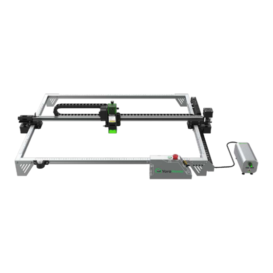
- Page 29 Part 2 Mechanical Installation Progress Check - Your assembly should now look like this - if it does not, verify the previous assembly steps!
- Page 30 Part 2 Mechanical Installation Step 12 Parts Required: ➔ Frame Assembly ➔ X Axis Gantry Rail Assembly (from Step 9) ➔ 5 M5x18 Screws With the Z Axis Assembly facing the front of the machine, place the X Axis Gantry Rail Assembly on top of the Right and Left Motor Assemblies.
- Page 31 Part 2 Mechanical Installation Step 13 CAREFULLY turn the machine upside down. Insert 1 M5x18 Screw from the underside of the Left Motor Assembly, securing the X Axis Gantry Assembly. Plug the 6-Pin connector into the stepper motor on the Left Motor Assembly.
- Page 32 Part 2 Mechanical Installation Step 14 Parts Required: ➔ Limit Switch Touch Plate ➔ 1 M5x25 Screw Install the Limit Switch Touch Plate onto the X Axis Gantry Rail, using the center hole on the Left Motor Assembly, as shown. The vertical part of the Limit Switch Touch Plate should be facing the inside of the frame.
- Page 33 Part 2 Mechanical Installation Step 15 Parts Required: ➔ X Axis Belt Tensioner The mounting screws for the X Axis Belt Tensioner are pre installed. Loosen the mounting screws slightly, and insert the Belt Tensioner on the left end of the X Axis Gantry Rail.
- Page 34 Part 2 Mechanical Installation Step 16 Parts Required: ➔ Timing Belt - X Axis Starting at the right side of the X Axis Gantry - Slide one end of the Timing Belt into the slot on the X Axis Gantry. Route the Timing Belt to the X Axis motor on the Right Motor Assembly, and around the...
- Page 35 Part 2 Mechanical Installation Step 16 Parts Required: ➔ Timing Belt - X Axis Route the Timing Belt along the back of the X Axis Gantry Rail, and through the Belt Tensioner - the belt must go on the inside of the Belt Tensioner housing, as shown.
- Page 36 Part 2 Mechanical Installation Step 17 Parts Required: ➔ Drag Chain Support Rail ➔ 3 M3x6 Screws Place the Drag Chain Support Rail on the rear side of the X Axis Rail; with the flat side of the support rail facing up. Using 3 M3x6 Screws, attach the Drag Chain Support Rail to the Left Motor Assembly, as shown.
- Page 37 Part 2 Mechanical Installation Step 18 Parts Required: ➔ Control Board (with Wiring and Drag Chain) ➔ 2 M5x20 Screws Place the Control Board in the right front corner of the machine frame. Route the wiring behind the right front foot, ensuring that the wiring is not “pinched”...
- Page 38 Part 2 Mechanical Installation Step 19 Route the Drag Chain and wiring along the right side of the machine. Ensure the Drag Chain is routed OVER the roller on the Drag Chain Support Bracket on the underside of the Right Side Motor Assembly.
- Page 39 Part 2 Mechanical Installation Step 20 Parts Required: ➔ 3 M3x6 Screws Using 3 M3x6 Screws, attach the Y Axis Drag Chain to the right front Frame Foot, as shown. Ensure that no wiring is caught under the screws.
- Page 40 Part 2 Mechanical Installation Step 21 Parts Required: ➔ 3 M3x6 Screws ➔ 3 M3x8 Screws Using 3 M3x6 Screws, attach the Y Axis Drag Chain to the Right Motor Assembly, as shown. M3x6 Using 3 M3x8 Screws, attach the X Axis M3x8 Drag Chain to the Right Motor Assembly, as shown.
- Page 41 Part 2 Mechanical Installation Step 22 Parts Required: ➔ 3 M3x6 Screws Using 3 M3x6 Screws, attach the X Axis Drag Chain to the X Axis Gantry Assembly, as shown.
- Page 42 Part 2 Mechanical Installation Step 23 Wire Connections - At the Right Motor Assembly, connect the Y Axis Motor harness which is underneath the X Axis Rail. Ensure that the wire is routed away from any rollers, using cable ties as needed.
- Page 43 Part 2 Mechanical Installation Step 23 Wire Connections - At the Right Motor Assembly, connect the X Axis Motor (upper motor) and Y Axis Motor (lower motor). Ensure that the wire is routed away from any rollers, using cable ties as needed.
- Page 44 At the X Axis Gantry, connect the Flame Detector Harness. Ensure that the wire is routed away from any rollers, using cable ties as needed. NOTE: FLAME DETECTION The 6550-Pro is equipped with a flame detection sensor, which will stop the machine in the event of fire detected in the engraving area (directly beneath the laser).
- Page 45 Part 2 Mechanical Installation Step 23 Wire Connections - At the rear of the X Axis Gantry, connect the X Axis Limit Switch harness. Ensure that the wire is routed away from any rollers, using cable ties as needed.
- Page 46 Part 2 Mechanical Installation Step 23 Wire Connections - At the right front corner, connect the Y Axis Limit Switch, which is underneath the Y Axis Rail. Ensure that the wire is routed away from any rollers, using cable ties as needed.
- Page 47 Part 2 Mechanical Installation Step 23 Wire Connections - In the front right corner of your machine, the stepper motor cable for your rotary can be plugged in to the provided 4-pin connector. To activate the rotary connection, use the Rotary switch on the back of the controller. Switching to the rotary will DISABLE both of the Y Axis motors;...
- Page 48 Part 2 Mechanical Installation Step 24 Parts Required: ➔ Laser Module Assembly ➔ 4 M3x8 Screws Using 4 M3x8 Screws, attach the Laser Module to the Z Axis, as shown.
- Page 49 Part 2 Mechanical Installation Step 25 Laser Module Connection Air Assist Connection Connect the Laser Module wire harness to the top of the laser module. Connect the Air Assist Tubing to the fitting on the bottom left of the laser module; this connection simply pushes in place.
- Page 50 Part 2 Mechanical Installation Step 26 Parts Required: ➔ Laser Height Gauge Holder ➔ 2 M5x20 Screws Using 2 M5x20 Screws, attach the Laser Height Gauge Holder to the front left corner of the frame, as shown.
- Page 51 Part 2 Mechanical Installation Step 26 Parts Required: ➔ Air Pump ➔ Air Pump Power Supply Attach the small length of tubing with the adapter fitting to the outlet of the Air Pump. Connect the Air Assist tubing from the front right corner of the machine to the outlet port of the Air Pump.
- Page 52 Part 2 Mechanical Installation Controller Information The following controls/ports are on the controller housing: Power: for 24VDC power supply Connect: USB to computer Memory Card: not used at this time Power Switch: turn machine on/off Estop - Emergency Stop: latches in safe position Warning: indicates flame detection has been initiated Offline Control (future use): will permit use of...
- Page 53 Part 2 Mechanical Installation Laser Focus Adjustment For proper laser operation, the focal height must be set from the work surface. Using the provided Laser Height Guide, adjust the height of the laser using the Z-Axis thumbscrew; setting the distance between the work surface and the bottom of the laser housing. The magnetic shield must be removed to set the height.
- Page 54 Part 2 Mechanical Installation Feet Adjustment (To Lift the machine or To Use Your Rotary Module) Parts Required: ➔ 8 Leg segments (50mm each) ➔ 4 T-slot nuts ➔ 4 Leg pads Using the T-slot nuts, attach one leg segment (50mm) to each corner of the frame to raise the machine.
- Page 55 NOTE FOR MAC USERS: If your Mac is running Mojave OS or higher, do NOT install the driver, as the OS has native support for the CH340. If you are running Sierra or High Sierra, please contact YoraHome Technical Support for additional guidance.
- Page 56 Part 3 Software Introduction Determine your machine COM’s port • Windows XP: Right click on My Computer, select Manage, then Device Manager. • Windows 7: Click on Start on the taskbar, right click on Computer, select Manage, then Device Manager. •...
- Page 57 Part 3 Software Introduction Install Your Laser Engraving Software LaserGRBL is one of the best Windows GCode streamers for DIY Laser Engravers. LaserGRBL is able to load and stream GCode path to your control board, as well engrave images, pictures and logos with internal conversion tool.
- Page 58 Part 3 Software Introduction - LaserGRBL Open the LaserGRBL Select the desired COM Software port, then click the “Connect” icon...
- Page 59 Part 3 Software Introduction - LaserGRBL Test your machine for proper motion control If the connection is using the “Jog” buttons - if the Y axis is successful, you will see the reversed, switch the motor cable to the other message below in the white port on the control board.
- Page 60 Part 3 Software Introduction - LaserGRBL To load an image for engraving, click on the “File” menu, then select “Open File”. In the Windows Explorer window; navigate to the desired image file on your computer. Common file types are JPG, BMP, PNG, SVG.
- Page 61 Part 3 Software Introduction - LaserGRBL Parameters default, click next You can use the default settings or adjust them - see our tutorial videos in YoraHome Facebook CNC Users Group or My YoraHome Knowledge Base for additional information.
- Page 62 Part 3 Software Introduction - LaserGRBL The engraving speed and MIN/MAX settings will need to be adjusted to meet the material being engraved. Note that the size values will automatically update whenever one is changed in order to maintain the aspect ratio of the origin image. Then click the “Create”...
- Page 63 Part 3 Software Introduction - LaserGRBL Using the jog buttons, position the laser to the lower left corner of the desired burn location; then click the “Globe” button to set the origin. Then click the “Play” button to start the laser engraving process.
- Page 64 Part 3 Software Introduction - Lightburn In the lower right of the screen, in the “Laser” pane, Open the Lightburn click on “Devices” Software...
- Page 65 Part 3 Software Introduction - Lightburn The “New Device Wizard” will start - select In the Devices dialog box, the “GRBL” option, and click “Next” click on the “Create Manually” button.
- Page 66 Part 3 Software Introduction - Lightburn If you would like to name the machine, you The default connection may do so here. Set the work area dimensions method should be as shown - X=650; Y=500 - click “Next”. “Serial/USB” - click “Next”.
- Page 67 Part 3 Software Introduction - Lightburn Set the origin for your laser - on the Confirm your settings, then click “Finish” 6550, that is the Front Left. If you wish to return to the Devices screen. to use the Auto-homing function, set that toggle to “True”...
- Page 68 Part 3 Software Introduction - Lightburn Click on “OK” to return to the main Lightburn screen.
- Page 69 Part 3 Software Introduction - Lightburn Click on the “File” menu, then select “Import” to open an image file.In the Windows Explorer window; navigate to the desired image file on your computer. Common file types are JPG, BMP, PNG, SVG.
- Page 70 Part 3 Software Introduction - Lightburn To set the engraving parameters, select the image on the grid, then go to the “Cuts/Layers” tab in the upper right pane (see next page for detail).
- Page 71 Part 3 Software Introduction - Lightburn Select your imported image, then select the parameters for your engraving - in the example below, we have selected a engraving speed of 1000 mm/min, at a power of 60%; with the mode set to “Fill”. This will direct the machine to burn the entire image and fill in the shape.
- Page 72 Part 3 Software Introduction - Lightburn Select the “Move” tab, and use the jog buttons to position your laser at the lower left corner of where the design is to be burned. Click on the “Set Origin” button to set the start position.
- Page 73 Part 3 Software Introduction - Lightburn Use the Power setting and the “Fire” button to turn the laser on at low power for focusing, click again to turn the laser off. If the “Fire” button is not visible, go to the Device Settings on the “Edit”...
- Page 74 Part 3 Software Introduction - Lightburn Finally, click on the “Start” button in the Laser pane to start the laser engraving process.
- Page 75 1, click on the Write button on the bottom of the window to store this information on the board, and reboot your machine. Q. How tight should my timing belts be on the 6550-Pro? A. Timing belts should be tight enough to not slip, but not so tight as to make smooth movement an operation’s issue.
- Page 76 WWW.YORAHOME.COM SUPPORT@YORAHOME.COM...
Need help?
Do you have a question about the 6550-PRO and is the answer not in the manual?
Questions and answers
what is power adapter volt
The power adapter voltage for the YoraHome 6550-PRO is 24V.
This answer is automatically generated