Table of Contents
Advertisement
Quick Links
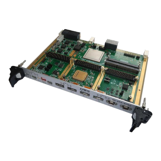
GR-VPX-XCKU060 Carrier Board
GR-VPX-XCKU060
Features
•
Xilinx XCKU060, in 1517 pin FCBGA package
•
GR716B (initially with GR716A)
microcontroller
•
SODIMM DDR3 up to 8 GiB
•
SPI flash for FPGA configuration (512 Mbit),
for GR716 boot (256 Mbit), and for data
(256 Mbit)
•
Power, Reset, Clock and Auxiliary circuits
•
Three FMC Mezzanine expansion connectors
•
Scrubbing interface for FPGA
•
Backplane I/F: SpaceWire (control),
SpaceFibre (data), VPX utility management
•
Frontplane I/F and drivers: 4x SpaceFibre,
2x SpaceWire, USB/FTDI UART/JTAG Links,
USB I/F to FMC
•
OpenVPX compatible, 6U format, Payload
profile
Description
The GR-VPX-XCKU060 board features a Xilinx
Kintex Ultrascale XCKU060 FPGA and a
GR716 microcontroller acting as a supervisor
for the FPGA. The board is equipped with
three VITA 57.1 FMC connectors. It can be
operated without any Mezzanine board but is
specifically designed to be used with 1 to 3
GR-HPCB-FMC-M2 Mezzanine Boards
connected, each with a Myriad™ 2 M2450
Processor. The GR-HPCB-FMC-M2 boards are
not included with the GR-VPX-XCKU060
board.
GR-VPX-XCKU060-DSUM
Mar 2022, Version 1.1
Specifications
•
System frequency GR716 uC: 20MHz, FPGA
XCKU060: 50 MHz
•
5 x SpaceFibre links rated @ 3.125 Gbps
and 2 x SpaceWire links @ 200 Mbps
•
CIF and LCD data interfaces 16-bit
running at 150 MHz. 24-bit interface
tested allowing upper bound 1.44Gb/s
full-duplex data transfer
•
Typical power consumption <10W (excluding
mezzanines)
•
DC supply via OpenVPX backplane connector
or via +5V/12V DC header for stand-alone
use
Applications
The board is a commercial development board for
prototyping of high-performance application such as:
•
Earth Observation optical and radar payload
processing
•
Multi- and hyperspectral data compression
•
Visual-Based Navigation acceleration
•
Video processing
•
AI/ML processing, such as:
Image segmentation (e.g. cloud
o
screening and removal)
Object detection (e.g. fire detection)
o
Pose estimation
o
The applications can be allocated to the on-board
FPGA or shared with technology implemented in up
to three Mezzanine boards, configured either for
increased performance or for redundancy
applications. The control and supervision of the
FPGA and Mezzanine boards is handled by a rad-
hard microcontroller.
Kungsgatan 12 | SE-411 19 Goteborg | Sweden
+46 31 7758650 | www.caes.com/gaisler
© Cobham Gaisler AB
Advertisement
Table of Contents

Summary of Contents for CAES GR-VPX-XCKU060
- Page 1 The board is a commercial development board for prototyping of high-performance application such as: • Earth Observation optical and radar payload Description processing The GR-VPX-XCKU060 board features a Xilinx • Multi- and hyperspectral data compression Kintex Ultrascale XCKU060 FPGA and a • Visual-Based Navigation acceleration GR716 microcontroller acting as a supervisor •...
-
Page 2: Table Of Contents
5.12 FMC Interfaces ........................26 5.12.1 Overview ........................26 5.12.2 FMC Interface Summary ..................... 26 5.12.3 LCD ..........................29 © Cobham Gaisler AB GR-VPX-XCKU060-DSUM Kungsgatan 12 | SE-411 19 Goteborg | Sweden Mar 2022, Version 1.1 +46 31 7758650 | www.caes.com/gaisler... - Page 3 5.17.1 D6 - FPGA initiation ....................44 5.17.2 D11 – VIN ........................44 5.17.3 D12 - PG_C2M ......................44 Mechanical Description ......................45 © Cobham Gaisler AB GR-VPX-XCKU060-DSUM Kungsgatan 12 | SE-411 19 Goteborg | Sweden Mar 2022, Version 1.1 +46 31 7758650 | www.caes.com/gaisler...
-
Page 4: Introduction
GR-VPX-XCKU060 INTRODUCTION Scope of the Document This document describes the design for the GR-VPX-XCKU060 Development Board. The main elements of this board are a Xilinx Kintex Ultrascale XCKU060 FPGA [RD1] and a GR716 microcontroller [RD2]. This board is designed and intended to be used with the GR-HPCB-MEZZ-M2 Mezza- nine Board but is conceived also to fulfil the requirements of standard VITA57.1 for FMC... -
Page 5: Document Revision Information
GR-VPX-XCKU060 HPCB-FMC-M2-DSUM https://www.xilinx.com/support/documentation/user_guides/ug575-ultrascale-pkg- [RD9] pinout.pdf GR-VPX-XCKU060 Board Package, see https://www.gaisler.com/index.php/prod- [RD10] ucts/boards/gr-vpx-xcku060 Document Revision Information Version Date Section / Page Description 2022-01-31 First approved issue. 2022-03-09 Page 1 Editorial corrections of “Applications” and RD references. Sec. 1.2 Abbreviations ASIC Application Specific Integrated Circuit. -
Page 6: Architecture
SLT6-PAY-4F1Q2T-10.2.1. The main components and functional blocks described in section 3. © Cobham Gaisler AB GR-VPX-XCKU060-DSUM Kungsgatan 12 | SE-411 19 Goteborg | Sweden Mar 2022, Version 1.1 +46 31 7758650 | www.caes.com/gaisler... -
Page 7: Configuration And Installation
FPGA pins, the complementary CLK0_M2C_N and CLK1_M2C_N are disconnected. Hence LVDS clocks cannot be used for these © Cobham Gaisler AB GR-VPX-XCKU060-DSUM Kungsgatan 12 | SE-411 19 Goteborg | Sweden Mar 2022, Version 1.1 +46 31 7758650 | www.caes.com/gaisler... -
Page 8: Functional Blocks
LVDS termination capabilities. • The DDR3 interface must operate with an I/O voltage of 1.5V. © Cobham Gaisler AB GR-VPX-XCKU060-DSUM Kungsgatan 12 | SE-411 19 Goteborg | Sweden Mar 2022, Version 1.1 +46 31 7758650 | www.caes.com/gaisler... -
Page 9: Gr716 Microcontroller
• SPIO1 as master for control/data connection to FMC circuits • 22 x GPIO connected to FPGA for signalling purposes Oscillators and Clock Inputs The oscillator and clock scheme for the GR-VPX-XCKU060 Board is shown in Figure 4 below. © Cobham Gaisler AB... -
Page 10: Reset Circuits
(nominally these are input clocks to the FPGA). Board level Clock Distribution Scheme – GR-VPX-XCKU060 Figure 4 Reset Circuits The reset scheme for the GR-VPX-XCKU060 Board is shown in Figure 5 below. The GR716 has its own internal reset circuitry. © Cobham Gaisler AB GR-VPX-XCKU060-DSUM Kungsgatan 12 | SE-411 19 Goteborg | Sweden Mar 2022, Version 1.1... -
Page 11: Power Supply And Voltage Regulation
Power Supply and Voltage Regulation Overview 4.6.1 The power supply system of the GR-VPX-XCKU060 board requires many voltages to be generated and distributed, some of which have high current requirements (e.g. FPGA core voltage). Typically, the power requirements must be over-dimensioned since the actual current con- sumption per rail is either unknown or varies depending on the application implemented in the FPGA logic. -
Page 12: Power Sequencing
Since some signals cross power domains, it will be necessary to carefully check the design for possible problems due to unintentional leakage across domains. The power scheme to be implemented on the GR-VPX-XCKU060 board is represented in Figure 6 below. - Page 13 ENABLE FMC-2 ENABLE FMC-1 Power Regulation Scheme – GR-VPX-XCKU060 Figure 6 The power sequencer is a UCD9090 10-rail PMBus/I C addressable power supply se- quencer and monitor which allows the monitoring of up to 10 voltage inputs and the pro- grammed sequencing multiple outputs.
-
Page 14: Fmc Power Supplies
GR-HPCB-FMC-M2 design to be able power up and shut down the circuits on the mezzanine board in a controlled manner. In this GR-VPX-XCKU060, the VADJ power supply connection to all the three FMC slots © Cobham Gaisler AB... -
Page 15: Interfaces
Interfaces are present on the front panel, on the backplane and as board-only interfaces. Locations with PCB designators are indicated in Figure 8 and Figure 9 below. © Cobham Gaisler AB GR-VPX-XCKU060-DSUM Kungsgatan 12 | SE-411 19 Goteborg | Sweden Mar 2022, Version 1.1 +46 31 7758650 | www.caes.com/gaisler... -
Page 16: Front Panel Interfaces
SpaceWire SPW-1 FPGA, bank 68 SpaceWire, LVDS FMC-USB USB hub, for further transfer to USB ports USB2.0 © Cobham Gaisler AB GR-VPX-XCKU060-DSUM Kungsgatan 12 | SE-411 19 Goteborg | Sweden Mar 2022, Version 1.1 +46 31 7758650 | www.caes.com/gaisler... -
Page 17: Backplane Interfaces
The on-board interfaces are listed below, major internal as well as those available by headers. On-board electrical interfaces Table 7 © Cobham Gaisler AB GR-VPX-XCKU060-DSUM Kungsgatan 12 | SE-411 19 Goteborg | Sweden Mar 2022, Version 1.1 +46 31 7758650 | www.caes.com/gaisler... -
Page 18: Spfi
57.1 lane name is indicated. For example, DP2 is composed of FMC pins A26, A27, A6 and A7 (signal names DP2_C2M_P, DP2_C2M_N, DP2_M2C_P and DP2_M2C_N). © Cobham Gaisler AB GR-VPX-XCKU060-DSUM Kungsgatan 12 | SE-411 19 Goteborg | Sweden Mar 2022, Version 1.1 +46 31 7758650 | www.caes.com/gaisler... - Page 19 FMC3-HPC1, DP1 Expansion Option 23 X1Y6, 225-2 FMC3-HPC2, DP2 Expansion Option 24 X1Y7, 225-3 FMC3-HPC3, DP3 Expansion Option © Cobham Gaisler AB GR-VPX-XCKU060-DSUM Kungsgatan 12 | SE-411 19 Goteborg | Sweden Mar 2022, Version 1.1 +46 31 7758650 | www.caes.com/gaisler...
-
Page 20: Spw Interfaces
The board implements up to three simultaneous SpaceWire Links distributed between the VPX backplane, GR716 microcontroller, Ultrascale FPGA, and External Front panel con- nectors. © Cobham Gaisler AB GR-VPX-XCKU060-DSUM Kungsgatan 12 | SE-411 19 Goteborg | Sweden Mar 2022, Version 1.1 +46 31 7758650 | www.caes.com/gaisler... - Page 21 • SpW links from the MDM connector on the front panel is routed to the FPGA In debug or stand-alone (without backplane) use © Cobham Gaisler AB GR-VPX-XCKU060-DSUM Kungsgatan 12 | SE-411 19 Goteborg | Sweden Mar 2022, Version 1.1 +46 31 7758650 | www.caes.com/gaisler...
-
Page 22: Spi
The GR716 microcontroller has two additional SPI interfaces with the GR716 acting as master. The first interface is connected to all the Myriad chips, sharing the MISO, MOSI © Cobham Gaisler AB GR-VPX-XCKU060-DSUM Kungsgatan 12 | SE-411 19 Goteborg | Sweden Mar 2022, Version 1.1 +46 31 7758650 | www.caes.com/gaisler... - Page 23 The GR716 operates as the Master of this interface. On-Board SPI Connections Figure 13 © Cobham Gaisler AB GR-VPX-XCKU060-DSUM Kungsgatan 12 | SE-411 19 Goteborg | Sweden Mar 2022, Version 1.1 +46 31 7758650 | www.caes.com/gaisler...
- Page 24 Slave 0: FMC1 Shared I2C interface for FMC Slave 1: FMC2 EEPROMs Slave 2: FMC3 On-Board I2C Connections Figure 14 © Cobham Gaisler AB GR-VPX-XCKU060-DSUM Kungsgatan 12 | SE-411 19 Goteborg | Sweden Mar 2022, Version 1.1 +46 31 7758650 | www.caes.com/gaisler...
-
Page 25: Ftdi (Usb Serial/Jtag)
The GR716 does not have any JTAG functionality. There are no connections to the VPX backplane JTAG pins. © Cobham Gaisler AB GR-VPX-XCKU060-DSUM Kungsgatan 12 | SE-411 19 Goteborg | Sweden Mar 2022, Version 1.1 +46 31 7758650 | www.caes.com/gaisler... -
Page 26: Usb
In the subsections below the details of the FMC interface are described. The naming on signals and references to Mezzanine board features targets the GR-HPCB-FMC-M2 board. The “Carrier Board” in the subsections below refers to this specific GR-VPX-XCKU060 board. Statements including the “M2” device refers to the Myriad™ 2 M2450 Processor. - Page 27 The pinouts for the three connectors are illustrated in Figure 16, Figure 17 and Figure 18 below. Signals are described in sub-sections that follow. P1 FMC connector pinout Figure 16 © Cobham Gaisler AB GR-VPX-XCKU060-DSUM Kungsgatan 12 | SE-411 19 Goteborg | Sweden Mar 2022, Version 1.1 +46 31 7758650 | www.caes.com/gaisler...
- Page 28 GR-VPX-XCKU060 P2 FMC connector pinout Figure 17 © Cobham Gaisler AB GR-VPX-XCKU060-DSUM Kungsgatan 12 | SE-411 19 Goteborg | Sweden Mar 2022, Version 1.1 +46 31 7758650 | www.caes.com/gaisler...
-
Page 29: Lcd
This is a data interface between the M2 and the FPGA on the Carrier Board comprising 29 signals: LCD[23..0] LCD_EN LCD_MCLK LCD_PCLK LCD_HSYNC LCD_VSYNC These signals use 1.8V signalling logic. © Cobham Gaisler AB GR-VPX-XCKU060-DSUM Kungsgatan 12 | SE-411 19 Goteborg | Sweden Mar 2022, Version 1.1 +46 31 7758650 | www.caes.com/gaisler... -
Page 30: Cif
These USB2 signals (DM, DP) connect via a 4-way USB hub on the Carrier Board to standard USB connector on the front panel. © Cobham Gaisler AB GR-VPX-XCKU060-DSUM Kungsgatan 12 | SE-411 19 Goteborg | Sweden Mar 2022, Version 1.1 +46 31 7758650 | www.caes.com/gaisler... -
Page 31: Jtag
RESET SUPERVISOR POWER SUPERVISOR POWER SUPERVISOR SUPERVISOR CIRCUITS CIRCUITS PUSH- PUSH- BUTTON BUTTON On-Board Reset Configuration Figure 20 © Cobham Gaisler AB GR-VPX-XCKU060-DSUM Kungsgatan 12 | SE-411 19 Goteborg | Sweden Mar 2022, Version 1.1 +46 31 7758650 | www.caes.com/gaisler... -
Page 32: Wakeup
The Logic Level of these signals is 1.8V and will be driven from the FPGA on the Carrier Board. These signals have an 'active low' logic where: © Cobham Gaisler AB GR-VPX-XCKU060-DSUM Kungsgatan 12 | SE-411 19 Goteborg | Sweden Mar 2022, Version 1.1 +46 31 7758650 | www.caes.com/gaisler... -
Page 33: I2C
VPX Backplane Interface 5.13 The overall connections to the VPX backplane are illustrated in the figure below. © Cobham Gaisler AB GR-VPX-XCKU060-DSUM Kungsgatan 12 | SE-411 19 Goteborg | Sweden Mar 2022, Version 1.1 +46 31 7758650 | www.caes.com/gaisler... - Page 34 Main +5V supply possible Row A Main +5V supply possible Row G GR716 I2C Row F GR716 I2C Row E © Cobham Gaisler AB GR-VPX-XCKU060-DSUM Kungsgatan 12 | SE-411 19 Goteborg | Sweden Mar 2022, Version 1.1 +46 31 7758650 | www.caes.com/gaisler...
- Page 35 Route to FPGA I/O, 1 sec PPS, input Row B AUX_CLK+ AUX_CLK_IN_P Route to FPGA I/O, 1 sec PPS, input Row A © Cobham Gaisler AB GR-VPX-XCKU060-DSUM Kungsgatan 12 | SE-411 19 Goteborg | Sweden Mar 2022, Version 1.1 +46 31 7758650 | www.caes.com/gaisler...
- Page 36 DP03-T0+ N.C. Row C Row B DP03-R0- N.C. Row A DP03-R0+ N.C. Row G Row F DP03-T1- N.C. © Cobham Gaisler AB GR-VPX-XCKU060-DSUM Kungsgatan 12 | SE-411 19 Goteborg | Sweden Mar 2022, Version 1.1 +46 31 7758650 | www.caes.com/gaisler...
- Page 37 Row E DP04-T3+ -"- -"- Row D Row C DP04-R3- -"- -"- Row B DP04-R3+ -"- -"- Row A © Cobham Gaisler AB GR-VPX-XCKU060-DSUM Kungsgatan 12 | SE-411 19 Goteborg | Sweden Mar 2022, Version 1.1 +46 31 7758650 | www.caes.com/gaisler...
- Page 38 Row G Row F Row E Row D Row C Row B Row A Row G Row F © Cobham Gaisler AB GR-VPX-XCKU060-DSUM Kungsgatan 12 | SE-411 19 Goteborg | Sweden Mar 2022, Version 1.1 +46 31 7758650 | www.caes.com/gaisler...
- Page 39 Row E CPtp01-DD+ -"- -"- Row D Row C CPtp01-DC- -"- -"- Row B CPtp01-DC+ -"- -"- Row A © Cobham Gaisler AB GR-VPX-XCKU060-DSUM Kungsgatan 12 | SE-411 19 Goteborg | Sweden Mar 2022, Version 1.1 +46 31 7758650 | www.caes.com/gaisler...
-
Page 40: Power
When this header is used, JP5 should be open to disconnect the FTDI-USB device (see section 5.16.5). J12 - Power 5.15.2 See section 5.14 above. © Cobham Gaisler AB GR-VPX-XCKU060-DSUM Kungsgatan 12 | SE-411 19 Goteborg | Sweden Mar 2022, Version 1.1 +46 31 7758650 | www.caes.com/gaisler... -
Page 41: J13 - Optional Sm-Bus
S2 - DIP Switch 5.16.1 The is a 4-pole DIP switch used to control GR716 DSU-Break and FPGA control signals USR[2..0]). © Cobham Gaisler AB GR-VPX-XCKU060-DSUM Kungsgatan 12 | SE-411 19 Goteborg | Sweden Mar 2022, Version 1.1 +46 31 7758650 | www.caes.com/gaisler... -
Page 42: Jp1 - Selectmap
GR-VPX-XCKU060 GR716 and FPGA configuration Figure 27 JP1 - SelectMAP 5.16.2 SelectMAP setting Figure 28 © Cobham Gaisler AB GR-VPX-XCKU060-DSUM Kungsgatan 12 | SE-411 19 Goteborg | Sweden Mar 2022, Version 1.1 +46 31 7758650 | www.caes.com/gaisler... -
Page 43: Jp2 - Fpga Spare
• EN0 closed • EN1 closed Configuration 3: GR716 connects to front panel, backplane link disabled S0 don’t care © Cobham Gaisler AB GR-VPX-XCKU060-DSUM Kungsgatan 12 | SE-411 19 Goteborg | Sweden Mar 2022, Version 1.1 +46 31 7758650 | www.caes.com/gaisler... -
Page 44: Jp4-Jp6 - Uart And Jtag Access
Detailed information for some LED functions follows below. D6 - FPGA initiation 5.17.1 D11 – VIN 5.17.2 D12 - PG_C2M 5.17.3 © Cobham Gaisler AB GR-VPX-XCKU060-DSUM Kungsgatan 12 | SE-411 19 Goteborg | Sweden Mar 2022, Version 1.1 +46 31 7758650 | www.caes.com/gaisler... -
Page 45: Mechanical Description
GR-VPX-XCKU060 MECHANICAL DESCRIPTION Top view Figure 32 © Cobham Gaisler AB GR-VPX-XCKU060-DSUM Kungsgatan 12 | SE-411 19 Goteborg | Sweden Mar 2022, Version 1.1 +46 31 7758650 | www.caes.com/gaisler... - Page 46 6U rack with a VPX Backplane. The dimensions of the main PCB are therefore 233.35x160mm (excluding the connector protrusions). © Cobham Gaisler AB GR-VPX-XCKU060-DSUM Kungsgatan 12 | SE-411 19 Goteborg | Sweden Mar 2022, Version 1.1 +46 31 7758650 | www.caes.com/gaisler...
- Page 47 • Mini/Micro USB connector for USB hub interface to FMC boards • Mini/Micro USB connector for FTDI interface (JTAG0/1 and UART0/1) • Push button switch (S1: RESET) © Cobham Gaisler AB GR-VPX-XCKU060-DSUM Kungsgatan 12 | SE-411 19 Goteborg | Sweden Mar 2022, Version 1.1 +46 31 7758650 | www.caes.com/gaisler...
- Page 48 Figure 35 The figure below illustrates a setup with three GR-HPCB-FMC-M2 boards installed. GR-VPX-XCKU060 Module concept Figure 36 © Cobham Gaisler AB GR-VPX-XCKU060-DSUM Kungsgatan 12 | SE-411 19 Goteborg | Sweden Mar 2022, Version 1.1 +46 31 7758650 | www.caes.com/gaisler...
- Page 49 Copyright © 2022 Cobham Gaisler AB GR-VPX-XCKU060-DSUM © Cobham Gaisler AB Mar 2022, Version 1.1 Kungsgatan 12 | SE-411 19 Goteborg | Sweden 49 of 49 +46 31 7758650 | www.caes.com/gaisler...
Need help?
Do you have a question about the GR-VPX-XCKU060 and is the answer not in the manual?
Questions and answers