
Related Manuals for JANUS INTERNATIONAL ASTA AMERICA 700 Series

Summary of Contents for JANUS INTERNATIONAL ASTA AMERICA 700 Series
- Page 1 COUNTER SHUTTERS 700 SERIES BASE INSTALLATION MANUAL READ ENTIRE MANUAL BEFORE BEGINNING INSTALLATION CARTERSVILLE,GA APRIL 2020 astaamerica.com...
- Page 2 SAFETY INFORMATION OVERVIEW OF POTENTIAL HAZARDS Counter Shutters are large, heavy objects that move with the help of springs under high tension and electric motors. Since moving objects, springs under tension, and electric motors can cause injuries, your safety and the safety of others depend on you reading the information in this manual.
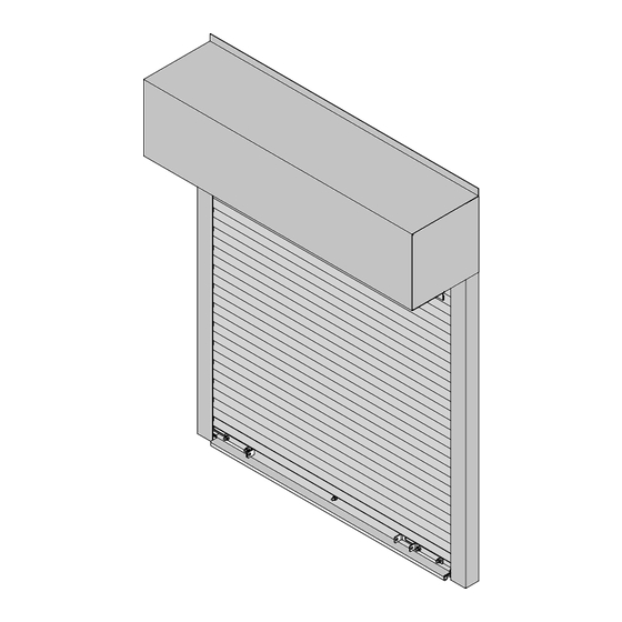
- Page 3 TYPICAL COUNTER SHUTTER ITEM DESCRIPTION DRIVE SIDE HEAD PLATE TENSION SIDE HEAD PLATE DRIVE SHAFT MOUNTING FASTENER (SEE FIG. 3) BARREL ASSEMBLY HOOD END COVERS FIGURE 1 TENSION SHAFT TENSION WHEEL BELLMOUTH/HEADSTOP BOTTOM BAR ASSEMBLY CURTAIN ASSEMBLY WALL GUIDE FRONT GUIDE PAGE 3 ASTA AMERICA...
- Page 4 3" X 3" CRUSH PLATE NUT WITH FOR SOFT BRICK FLAT WASHER OR UNFILLED CMU ALL THREAD STUD THRU WALL CONCRETE ANCHOR (1/4" SETBACK) (1/4" SETBACK) FILLED CONCRETE UNFILLED CONCRETE MASONRY UNIT MASONRY UNIT LAG BOLT (3/8" X 3") LAG BOLT (3/8" X 3") THREAD CUTTING SCREW THREAD CUTTING SCREW (1/4"...
- Page 5 FASTENER CHART DRILL NOTES JAMB FASTENER SIZE 3/8-16 X 1-1/4" TYPE 23 THD CUT SCREW 11/32" 3/16" THICK STEEL JAMB MINIMUM 3/8-16 X 1-1/4" HEX BOLT AND NUT 7/16" STEEL 1/8" 3/8 LAG SCREW CONCRETE 3/8" 3/8" X 1-7/8" SLEEVE ANCHOR CLEAR HOLES OF CONCRETE DUST BEFORE INSTALLING FASTENER FILLED BLOCK...
- Page 6 Procedure for shooting level reference marks Create level elevation marks at left and right jamb faces using a level reference device or survey instrument as shown in Figure 6. ü Be positive about the accuracy of your level elevation reference marks! LEVEL REFERENCE FIGURE 6...
- Page 7 TAPE MEASURE "W" DIMENSION MARKS ON SILL SILL FIGURE 7 Use a tape measure while attaching the second wall angle to maintain a consistent "W" dimension all the way to the top as shown in Figure 7. ü Verify that the low side wall angle is shimmed to the correct height before permanent attachment to the jamb.
- Page 8 Procedure for assembling barrel and headplate assemblies. Proceed at ground level and identify components as shown in Figures 8, 9 and 10. HEADPLATES BARREL ASSEMBLY TENSION SIDE DRIVE SIDE HEADPLATE HEADPLATE TENSION END DRIVE SIDE BEARING BEARING IF MANUAL FACTORY WELDS INSTALLED TENSION PIN...
- Page 9 Procedure for installing barrel and headplates to guide assembly Carefully secure barrel to hoisting equipment and raise into position at top of wall angles. Attach headplate brackets to wall angles as shown in Figure 10. VERIFY THAT BARREL IS DEAD LEVEL BEFORE INSTALLING WALL & HEADPLATE FASTENERS.
- Page 10 CAUTION FIGURE 11 It may be necessary to use the hoisting equipment to lift the weight of the curtain ü enough to allow rotation of the barrel to bring the attachment lugs into position with segmented starter slats. ü When starter slats are attached to the barrel lugs, you may lower the hoisting equipment and proceed with the next step.
- Page 11 Procedure for applying preload to barrel assembly Roll curtain to fully closed position. Apply tension from the top, downward, as shown in Figure 13 to the preload amount shown on tension headplate label, barrel sticker, or shop drawing. Raise curtain and check balance. FIGURE 13 Procedure for installing hood flange, hood and endcovers.
- Page 12 Appendix "A" Procedure for Installing (optional) Awning Crank Insert 1/4" x 1" key stock into key seat on drive shaft. Align bevel gear key way with key stock and slide awning crank onto drive shaft until awning crank back is seated against head plate. Align mounting holes in awning crank with mounting holes in head plate.
Need help?
Do you have a question about the ASTA AMERICA 700 Series and is the answer not in the manual?
Questions and answers