
Summary of Contents for Cyndar Electronic Technology XD-TOF-25
- Page 1 XD-TOF-25Lidar sensor operating instructions Single-line Lidar Product Manual Series ・Product specification description ・Product operating instructions ・Product communication methods and protocols...
-
Page 2: Table Of Contents
Table of Contents ..........2 About ........3 Product description ......3 Equipment Specifications ........ 5 Working principle ....7 Influence of object surface on measurement ........9 Ranging error ........9 Area alarm ........ 11 Equipment appearance ...... -
Page 3: About
XD-TOF-25 are proposed: the network port is connected to the "TCP/IP" protocol The terminal outputs the distance information of the target object in the scanning area. -
Page 4: Product Description
Product description Equipment Specifications Table 2-1 XD-TOF-25 equipment specification list Parameter XD-TOF-25 Detection distance 0.05-25m Light source wavelength 905nm Laser class Minimum response time ≤66ms Angular resolution 0.33° Output resolution 1.0mm Interface Ethernet Operating temperature -10°~50° Radar module Voltage 9-30V Power consumption <... - Page 5 Table 2-3 Environmental adaptability parameters IP67 Chassis protection level Level GB 7247.1-2012 Laser radiation safety level Conduction CE A grade industrial grade GBT_17626.6-2008 Conduction CS GBT_17626.6-2008 Level 3 10V/M Level 5 100A/M GBT_17626.8-2006 Power frequency magnetic field Voltage drop 40%、70%、80%、120% GBT_17626.29-2006 Electrostatic discharge Level 2 4KV...
-
Page 6: Working Principle
Schematic diagram of the range measurement principle of the lidar sensor The XD-TOF-25 lidar sensor emits laser pulses through a laser diode, and after related processing, it becomes a Gaussian distributed circular spot and emits at a certain divergence angle. The beam exit diameter is 8mm. As the detection distance increases, Figure 2-3 visually shows the beam divergence process, and Figure 2-4 shows the curve of the spot size at different distances. - Page 7 D = 3mm + 0.010rad × U(mm) The relationship between the spot diameter D and the detection distance U is: Distance(m) Figure 2-4 Laser beam diameter at different detection distances As shown in Figure 2-6, when the object to be measured at a specific distance is larger than the spot size of the laser, the object to be tested can be stably detected.
-
Page 8: Influence Of Object Surface On Measurement
The existing angular resolution of XD-TOF-25 is 0.33°. There are 811 laser pulses for each pair of two-dimensional plane scans. As shown in Figure 2-7... - Page 9 The minimum detectable reflec- tance curve of XD-TOF-25 series products is shown in Figure 2-8: the vertical axis of the curve is the mini- mum detectable reflection Rate (equivalent reflectance), the abscissa is the corresponding distance.
-
Page 10: Ranging Error
30mm of error distribution The output range of XD-TOF-25 is 50mm-25000mm (the actual output is hexadecimal ASCII code, 1mm corresponds to 1h, ASCII code 30 30 30 31, 25000mm corresponds to 61A8h, ASCII code is 36 32 40 38, the specific format and details please (Refer to the section on data communication in Section 4 Device Connection). -
Page 11: Area Alarm
Within the measurement range, XD-TOF-25 integrates two different area alarm methods. Method one: Set through the client application TCPClient of XD-TOF-25; users can link with radar through TCPClient and set any polygonal alarm area. When foreign objects invade the alarm area, TCP- Client will flash the red icon and trigger an alarm bell. -
Page 12: Equipment Appearance
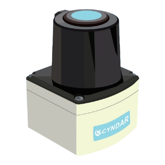
Equipment appearance The overall dimensions and overall installation diagram are as follows. Unmarked units default to millimeters. Figure 6 Overall installation effect Sensing the world · Leading the change... - Page 13 As shown in the figure, the front of the device is the status indicator, the horizontal center line is the plane where the laser scanning optical axis is located, and the laser is emitted through the infrared protective cover. Please pay attention to the maintenance of the protective cover during use.
-
Page 14: Device Connection
Device connection Main interface The main view of the plane where the two interfaces are located is as follows: Figure 7 Device external interface The two interfaces from left to right are: network interface, I/O interface, data interface and power interface. More detailed information is listed in the table below. Sensing the world ·... -
Page 15: Device Connection And Communication
, Define, clear and other operations, you need to design according to the actual situation). STEP1: Place the XD-TOF-25 lidar sensor in a suitable position so that it can scan the area you need. - Page 16 STEPA3: DC power supply output power supply. At this time, the status display on the front of the device lights up. When the green OK display light is on, the XD-TOF-25 lidar sensor starts to scan within the scanned area.
- Page 17 A8h (hexadecimal, 41 38 corresponding to 168) Space(SPC) 00h (two-byte hexa- 30 30 decimal, correspond- ing to 0) Space(SPC) 02h (two-byte hexa- 30 32 decimal, correspond- ing to 2) Footer <ETX> The command to set the gateway is: (set to 192.168.0.1) <STX>sWN{SPC}Elgate{SPC}C0{SPC}A8{SPC}00{SPC}01<ETX>...
- Page 18 STEP5:Log in to the device as a client sending commands Before officially starting communication, the communication format of XD-TOF-25 is first introduced. The communication method of XD-TOF-25 is composed of hexadeci- mal byte ASCII codes, and its formats include: Table 4-3 Communication data packet format...
- Page 19 Actual sending 73 4D 4E 53 65 74 41 63 63 65 73 73 4D 6F 64 65 instruction (Hex) 46 34 37 32 34 37 34 34 Header <STX> 73 4D 4E Space(SPC) SetAccessMode 53 65 74 41 63 63 65 73 73 4D 6F 64 65 Space(SPC)...
- Page 20 while (clientStream.DataAvailable); //If the data does not arrive, the loop is received You can continue to operate the acceptance information in myCompleteMessage to determine further operations. The following continues to extract key instruction information, which may contain ETX, STX, you need to further elaborate processing string result = myCompleteMessage.ToString();...
- Page 21 myCompleteMessage.AppendFormat("{0}",Encoding.ASCII.GetString(nameanswer, 0, numberOfBytesRead)); //Write all the information stack read by the network port to the receiving result variable while (clientStream.DataAvailable); //If the data does not arrive, the loop is received You can continue to operate the acceptance information in myCompleteMessage to determine further operations. The following continues to extract key instruction information, which may contain ETX, STX, you need to further elaborate processing string result = myCompleteMessage.ToString();...
- Page 22 numberofBytesRead = clientStream.Read(identanswer, 0, identanswer.Length); //Read TCPIP communication receive buffer myCompleteMessage.AppendFormat("{0}",Encoding.ASCII.GetString(identanswer, 0, numberOfBytesRead)); //Write all the information stack read by the network port to the receiving result variable while (clientStream.DataAvailable); //If the data does not arrive, the loop is received You can continue to operate the acceptance information in myCompleteMessage to determine further operations.
- Page 23 (error) Footer <ETX> (Routine 5) Read device status byte[] status ={ 0x02, 0x73, 0x52, 0x4E, 0x20, 0x4C, 0x43, 0x4D, 0x73, 0x74, 0x61, 0x74, 0x65, 0x03 }; //Ask device status clientStream.Write(status, 0, status.Length); //Send login instruction to radar if (clientStream.CanRead) byte[] stateanswer = new byte[1024]; //Open up cache StringBuilder myCompleteMessage = new StringBuilder();...
- Page 24 Actual sending 73 4D 4E 6D 4C 4D 50 73 65 74 73 63 61 6E 63 66 command 35 44 43 37 44 30 46 46 46 39 32 32 15Hz/0.2° (Hex) 33 30 32 32 35 35 31 30 Header <STX>...
- Page 25 73 41 4E 6D 4C 4D 50 73 65 74 73 63 61 6E 63 66 67 Actual receive 35 44 43 44 30 35 46 46 46 39 32 32 33 30 command 0.33 (Hex) 32 32 35 35 31 30 73 41 4E 6D 4C 4D 50 73 65 74 73 63 61 6E 63 66 67 Actual...
- Page 26 clientStream.Write(setscancfg50, 0, setscancfg50); //Send login instruction to radar if (clientStream.CanRead) byte[] scancfganwser = new byte[1024]; //Open up cache Receive result variable StringBuilder myCompleteMessage = new StringBuilder(); // int numberOfBytesRead = 0; numberofBytesRead = clientStream.Read(scancfganwser, 0, scancfganwser.Length); //Read and remove TCPIP communication receive buffer myCompleteMessage.AppendFormat("{0}",Encoding.ASCII.GetString(scancfganwser, 0, numberOfBytesRead));...
- Page 27 Actual 73 52 41 6D 4C 4D 50 73 65 74 73 63 61 6E 63 66 67 receiving 35 44 43 37 44 30 46 46 46 39 32 32 33 30 instruction 0.2°(Hex) 32 35 35 31 30 Header <STX>...
- Page 28 Space(SPC) Data 1 (configurable area) content Space(SPC) Speed 1500(50Hz) 35 44 43 configuration Space(SPC) 0(0)(0°) Optional configuration I (data output start angle) Space(SPC) Optional configuration II (end angle of DBBA0(900000)(90°) 44 42 42 41 30 data output) Footer <ETX> For the XD-TOF-series, this command can optionally configure the starting angle (-45°) and ending angle (+225°).
- Page 29 byte[]outputRangeanwser = new byte[1024]; //Open up cache StringBuilder myCompleteMessage = new StringBuilder(); //Receive result variable int numberOfBytesRead = 0; numberofBytesRead = clientStream.Read(outputRangeanwser, 0, outputRangeanwser.Length); //Read TCPIP communication receive buffer myCompleteMessage.AppendFormat("{0}",Encoding.ASCII.GetString(outputRangeanwser, 0, numberOfBytesRead)); //Write all the information stack read by the network port to the receiving result variable while (clientStream.DataAvailable);...
- Page 30 Space(SPC) Optional configura- 0(0)(0°) tion I (data output start angle) Optional configura- tion II (end angle of D BBA0 ( 90000 0)(90°) 44 42 42 41 30 data output) Footer <ETX> STEP13:Store current configuration The current configuration of the radar can be written into the memory by sending this command, so that it will continue to maintain the current configuration at the next power-up, so this command must be sent after some confirmed modifications.
- Page 31 if (clientStream.CanRead) byte[] writeanwser = new byte[1024]; //Open up cache StringBuilder myCompleteMessage = new StringBuilder(); //Receive result variable int numberOfBytesRead = 0; numberofBytesRead = clientStream.Read(writeanwser, 0, writeanwser.Length); //Read TCPIP communication receive buffer myCompleteMessage.AppendFormat("{0}",Encoding.ASCII.GetString(writeanwser, 0, numberOfBytesRead)); //Write all the information stack read by the network port to the receiving result variable while (clientStream.DataAvailable);...
- Page 32 STEP15: Log out and exit the current authority and run the radar according to the configuration <STX>sMN{SPC}Run<ETX> Instruction 73 4D 4E 52 75 6E Actual sending instruction (Hex) Header <STX> 73 4D 4E Space(SPC) 52 75 6E Footer <ETX> When the radar is operating normally, you will receive: <STX>sAN{SPC}Run{SPC}1<ETX>...
- Page 33 ※For a single data request, the XD-TOF-25 radar will send the data obtained from the last scan to ensure that the customer receives the timeliness of the data, as shown in the following figure, so the longest delay may result in 66ms between the output data and the request time Delay.
- Page 34 Space(SPC) Device start 00000000—FFFFFFFF 30 30 30 30 30 30 30 30 timer —46 46 46 46 46 46 46 46 Space(SPC) 00000000 —FFFFFFFF Packet wait 30 30 30 30 30 30 30 30 timer —46 46 46 46 46 46 46 46 Space(SPC)...
- Page 35 Data content ASCII code to hexa- XX XX XX XX为数据的 16 进制 ASCII 码, decimal number, and XD-TOF-25 对应 16进制数据范围为 0000h then convert the (30 30 30 30 )到 61A8h(36 31 41 38) hexadecimal number to decimal number,...
- Page 36 Read TCPIP communication receive buffer myCompleteMessage.AppendFormat("{0}",Encoding.ASCII.GetString(runanwser, 0, numberOfBytesRead)); Write all the information stack read by the network port to the receiving result variable while (scandata[numberOfBytesRead—1] != 0x03);//Because the multi-segment PSH=1 is used for segment transmission, it must detect the trailer (ETX, 03h) before it is considered that the reception is complete.
- Page 37 Space(SPC) Start continuous ranging Footer <ETX> After the radar receives the continuous data request, it will immediately respond to your application with a continuous mode confirmation instruction, indicating that the radar has received the instruction from your client and enters the continuous ranging mode.
- Page 38 Space(SPC) Stop continuous ranging Footer <ETX> After the radar receives your stop command, it will immediately stop sending the next frame of data packets and send a confirmation stop command to your application client: <STX>sEA{SPC}LMDscandata{SPC}0<ETX> 73 45 41 4C 4D 44 73 63 61 6E 64 61 74 61 Header <STX>...
- Page 39 The radar will reply to you after receiving the order (for example, 2999.7 hours): <STX>sRA{SPC}ODpwrc{SPC}752D<ETX> 73 52 41 4F 44 70 77 72 63 752D Header <STX> 73 52 4E Data Space(SPC) content ODpwrc 4F 44 70 77 72 63 Space(SPC)...
-
Page 40: Operation Routine
Space(SPC) Distance of XXXX (4-digit ASCII XX XX XX XX alarm point 1 in code) Example: 7D0 37 64 30 polar coordi- (7D0 unit mm, nate system 2000mm) Space(SPC) Alarm point 2 angle XXXX XX XX XX XX Space(SPC) Distance of alarm point 1 XXXX XX XX XX XX... - Page 41 The TCP/IP communication process will send large packets of data in segments, and the maximum length of a single segment is 1460 bytes. For XD-TOF-25, the length of the data packet containing the scanned data can reach 4468 bytes. This means that a data...
- Page 42 Contact us English website: www.gzcyndar.com email:sales1@cyndar.net...
Need help?
Do you have a question about the XD-TOF-25 and is the answer not in the manual?
Questions and answers