Table of Contents
Advertisement
Quick Links
Advertisement
Table of Contents

Related Manuals for Proyecson PAA20+

Summary of Contents for Proyecson PAA20+
- Page 1 INSTALLATION MANUAL PAA20+ V 2.0...
- Page 2 Imprint All rights reserved © Copyright by Proyecson S.A. Ronda Guglielmo Marconi 4. Parque Tecnológico. 46980 Paterna (Valencia) Spain Printed in Spain. Oct 2021. This operating manual even in ex- tracts may only be reprinted or oth- erwise copied with special, written permission from Proyecson S.A.
-
Page 3: Table Of Contents
TABLE OF CONTENTS 1. SAFETY.....................6 1.1 GENERAL.......................6 1.2 INSTALLATION....................6 1.3 PROPER USE....................7 2. INTRODUCTION................8 3. FEATURES..................9 4. FRONTAL PANEL................11 5. REAR PANEL..................12 6. CONNECTION PROCEDURE..............13 6.1 CONNECTION TO DOLBY DSS SERVERS............13 6.2 CONNECTION TO DOREMI DCP SERVERS OVER ETHERNET.........14 6.3 CONNECTION TO DOREMI DCP SERVERS USING SERIAL PORT......15 6.4 CONNECTION TO GDC SERVERS OVER ETHERNET..........16 6.5 CONNECTION TO GDC SERVERS USING THE SERIAL PORT.........17 6.6 CONNECTION TO QUBE XP-D SERVER USING THE SERIAL PORT......18... - Page 4 8.4.1 Adding the PAA20+ to Barco Alchemy ICMP servers: Ethernet interface..77 8.4.3 Setting up the output cues for Barco Alchemy ICMP servers using xml library. 84 8.4.4 Setting up the PAA20+inputs for Barco Alchemy ICMP servers......87 8.5 GDC SERVER SET-UP..................91 8.5.1 Adding the PAA20+ to the GDC server: Ethernet interface......91...
- Page 5 APPENDIX F: COMMANDS FOR QUBE SERVERS........132 APPENDIX G: QUBE AUTOMATION FILES EXAMPLES......134 APPENDIX H: COMMANDS FOR BARCO ALCHEMY (ICMP) AND CHRISTIE IMB S2....................146 APPENDIX I: COMMANDS FOR BARCO ALCHEMY (ICMP) REMOTE PLAYER MANAGEMENT..............148 INSTALLATION MANUAL: PAA20+ V 2.0 (10/2021)
-
Page 6: Safety
1. SAFETY 1.1 GENERAL IMPORTANT: READ THIS MANUAL BEFORE INSTALLING AND OPER- ATING THE DEVICE. This device is for indoor use only. Do not install outdoor without an ap- • propriate weather protection. Never modify or handle the mechanical or electrical safety devices in- •... -
Page 7: Proper Use
1.3 PROPER USE Do not use this device if you have not previously received the necessary • instructions of safety, use and cleaning by an expert user. Read and understand the operating manual of this device before using. • Always disconnect the device before cleaning or any kind of maintenance •... -
Page 8: Introduction
2. INTRODUCTION The Proyecson PAA20+ Automation adapter makes it easy to interface digital cinema playback equipment with existing cinema control systems, allowing thus fully automated presentations. Input and output connections enable digital cinema equipment to control existing lighting, automation, and other old systems. The unit converts network or serial control signal from the digital cinema playback system in relay closures. -
Page 9: Features
3. FEATURES PAA20+ Front Panel LED Indicator General purpose input, relay output status, 24V and 3.3V. Test Buttons Buttons for test and manually activation purposes for each input/output. PAA20+ Rear Panel Connections General Purpose Inputs Eight opto-isolated low- voltage inputs, screw terminals, 24V logics. - Page 10 Power Requirements Disclaimer of Warranties 1) 100-240 VAC, 50-60 Hz Equipment manufactured by Proyecson S.A. is warranted against defects in 2) 24 VDC, 2 A materials for a period of one year from the date of purchase. There are no other...
-
Page 11: Frontal Panel
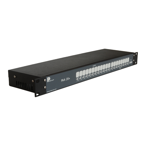
4. FRONTAL PANEL Figure 4.A 1. 24vdc indicator 2. 3.3vdc indicator 3. Activity indicator 4. Manual activation buttons and output active status leds. The led indicates that the output is active. • Activate the outputs directly with the pushbuttons without using •... -
Page 12: Rear Panel
5. REAR PANEL Figure 5.A 1. Main power supply input 100 - 230 VAC. 2. Inputs connector. 3. Outputs connectors. 4. RJ45 network connection port with connection and activity leds indic- ator. 5. 9 pin female D-connector serial port. 6. 24VDC auxiliary power supply input. INSTALLATION MANUAL: PAA20+ V 2.0 (10/2021) -
Page 13: Connection Procedure
6. CONNECTION PROCEDURE 6.1 CONNECTION TO DOLBY DSS SERVERS The PAA20+ must be connected to a Dolby DSS100, DSS200 or DSS220 servers through port RS232. Connect the RS232 serial port of the Dolby server to the RS232 serial port of the PAA20+ using a pin to pin male to female standard serial cable. -
Page 14: Connection To Doremi Dcp Servers Over Ethernet
6.2 CONNECTION TO DOREMI DCP SERVERS OVER ETHERNET The connection of the PAA20+ to any Doremi server can be done through the Ethernet port. The PAA20+ must be added to the Doremi server as a new device and send/receive commands configured as explained throughout this manual. See the interconnection diagram on the following picture: Figure 6.2C INSTALLATION MANUAL: PAA20+ V 2.0 (10/2021) -
Page 15: Connection To Doremi Dcp Servers Using Serial Port
6.3 CONNECTION TO DOREMI DCP SERVERS USING SERIAL PORT Only DCP200, DCP2K4 and ShouVault Doremi servers with 2.0.5.0 or higher software version could be connected to PAA20+ using the serial port. It is not possible to connect the IMS1000 server with the PAA20+ using the serial port. -
Page 16: Connection To Gdc Servers Over Ethernet
6.4 CONNECTION TO GDC SERVERS OVER ETHERNET The connection of the PAA20+ to any GDC server can be done through the Ethernet port. The PAA20+ must be added to the GDC server as a new device and output/input commands configured as explained throughout this manual. See the interconnection diagram on the following picture: Figure 6.4A INSTALLATION MANUAL: PAA20+ V 2.0 (10/2021) -
Page 17: Connection To Gdc Servers Using The Serial Port
6.5 CONNECTION TO GDC SERVERS USING THE SERIAL PORT Only SX-2001, SX-2000A and SX-2000AR GDC servers could be connected to PAA20+ using the serial port. It is not possible to connect the SX-3000 server with the PAA20+ using the serial port. The PAA20+ must be added to the GDC server as a new device and output/input commands configured as explained throughout this manual. -
Page 18: Connection To Qube Xp-D Server Using The Serial Port
6.6 CONNECTION TO QUBE XP-D SERVER USING THE SERIAL PORT The connection of the PAA20+ to a Qube XP-D server can be done using the serial port. The PAA20+ must be added to the Qube server as a new device and output/input commands configured as explained throughout this manual. -
Page 19: Connection To Datasat Dc20 Server Using Serial Port
6.7 CONNECTION TO DATASAT DC20 SERVER USING SERIAL PORT The connection of the PAA20+ to a Datasat DC20 server can be done using the serial port. The PAA20+ must be added to the Datasat server as a new device and output/input commands configured as explained throughout this manual. -
Page 20: Connection To Barco Alchemy (Icmp) Over Ethernet
6.8 CONNECTION TO BARCO ALCHEMY (ICMP) OVER ETHERNET The connection of the PAA20+ to a Barco Alchemy (ICMP) server can be done through the Ethernet port. The physical Ethernet port used for the Alchemy to communicate with the automation devices is the same used for the projector control. -
Page 21: Connection To Ims Servers Over Ethernet
6.9 CONNECTION TO IMS SERVERS OVER ETHERNET The connection of the PAA20+ to any Doremi, Dolby or NEC IMS server can be done through the Ethernet port. The PAA20+ must be added to IMS server as a new device and send/receive commands configured as explained throughout this manual. -
Page 22: Connection To Christie Imb S2 Server Over Ethernet
6.10 CONNECTION TO CHRISTIE IMB S2 SERVER OVER ETHERNET The connection of the PAA20+ to the Christie IMB S2 server must be done through the Ethernet port. The PAA20+ must be added to IMB S2 server as a new device and send/receive commands configured as explained throughout this manual. -
Page 23: Administration Of The Paa20
FTP:ftp://manual:proyecson@ftp3.proyecson.com/manual/paa20+ search the device. The installation and use procedures for this program are described APPENDIX PAA20+TESTER PROGRAMMER SOFTWARE . It is possible to reset the unit to factory configuration using the reset button located in the front. If you keep the button pressed for more than tree seconds, until the “status”... -
Page 24: Paa20+ Web Admin Interface
7.2 PAA20+ WEB ADMIN INTERFACE. The interface displays a menu in the left side of the page where you can se- lect different options. 7.2.1 STATUS PAGE. Figure 7.2.1A The first and initial page of the Web Admin interface is the “Status” page. In this page you can check the state of the inputs and outputs of the device, as well as the firmware, the Ethernet stack version and the temperature inside the PAA20+ in degrees Celsius. - Page 25 Figure 7.2.2A. To obtain the password for the administrator level please contact with an authorized Proyecson dealer. Once you introduced the correct user and password in the pop-up window you will gain full control of the PAA20+.
- Page 26 7.2.3 REMOTE CONTROL PAGE. Figure 7.2.3A The remote control page allows you to switch the output relays and to remotely test the inputs. To toggle the output relay, click on the state indicator, on the right side of the output number. The state indicator will appear in green and If the switch is on or gray if it is off.
- Page 27 7.2.4 TCP/IP CONFIGURATION PAGE. Figure 7.2.4AI In this page you can configure the TCP/IP interface of the PAA20+. The configuration shown in the Figure 7.2.4A is the factory one, thus this is the configuration you will find in a brand new unit. To change the configuration simply write a new value in the corresponding field and store it using the “save”...
- Page 28 Be careful when changing TCP/IP parameters. Wrong configuration could cause the lost of communication with the PAA20+. You will possibly need to reset the TCP/IP configuration to its factory default. If you enable the DHCP option, be sure that you have a DHCP server enabled in the network were you are going to connect the PAA20+.
- Page 29 7.2.5 AUTOMATION OUTPUT CONFIGURATION PAGE. Figure 7.2.5AI The Automation Output Configuration page is the interface to set up the reception of messages from the server and the relay performance. To store the changes of every individual relay click on the “Save” button located at the right side of the “Relay n pulse”...
- Page 30 Messages in the Figures are the factory default messages, compatible with both Dolby Doremi configuration files available FTP: ftp://manual:proyecson@ftp3.proyecson.com/manual/paa20+. change messages, write down new ones in the associated textbox and press the save button to the right. INSTALLATION MANUAL: PAA20+ V 2.0 (10/2021)
- Page 31 Figure 7.2.5C Output Message Terminator: This field lets you choose the message terminator for output messages. You can choose between: - “Return command”, 0x0D in hexadecimal. • - “New line command”, 0x0A in hexadecimal. • \r\n - “Enter command”, a return command followed by a new line •...
- Page 32 Figure 7.2.5D Actual firmware version limits the message length to seven characters in these fields. Should you modify the factory default messages, use of the provided Dolby and Doremi server configuration files is not advisee because messages will not match. INSTALLATION MANUAL: PAA20+ V 2.0 (10/2021)
- Page 33 7.2.6 AUTOMATION INPUT CONFIGURATION PAGE. Figure 7.2.6A The Automation Input Configuration page is the interface to setup the messages sent to the server. Figure 7.2.6A shows a snapshoot of the page. Values shown in the figure are factory defaults. To store changes proceed as in the previous page. Inputs: Field to choose if you want to send cue messages via the Ethernet interface or the Serial...
- Page 34 Messages in the Figures are factory default messages compatible with Dolby configuration files available FTP: ftp://manual:proyecson@ftp3.proyecson.com/manual/paa20+. change messages, write down new ones in the associated textbox and press the save button to the right side of each one. Server selection: With the actual firmware version it is possible to load pre-configured messages for Doremi and Qube servers input signals.
- Page 35 If you select a Doremi server, a popup window alerts you about the necessity of setting the Input Message Terminator to “\r\n”. Figure 7.2.6.D shows this popup window. Figure 7.2.6D After the Doremi server selection is done, the Automation Input Configuration page look as you can see in the Figure 7.2.6E.
- Page 36 This “Update” button fills in the “Input n” fields with the Doremi server input messages, but does not save them. You must save every input individually to store the message string into the PAA20+ data memory. Every time you save an Input field, the other ones return to their stored values as you can see in the example showed in Figure 7.2.6F, where we saved the Input 1 value.
- Page 37 Figure 7.2.6G The “Default” selection fills in the “Input n” fields to the factory default messages. Input Message Terminator: As in the Output page, this field let you choose the message terminator for Input messages. You can choose between: - “Return command”, 0x0D in hexadecimal. •...
- Page 38 7.2.7 ADVANCED CONFIGURATION PAGE. Figure 7.2.7A Using the Advanced Configuration page it is possible to set some special features of the PAA20+. Figure 7.2.7A shows a snapshot of the top of this page. The advanced features in this firmware version are the “Input Link” and the “Startup State”.
- Page 39 Figure 7.2.7B Figure 7.2.7C shows you an example to activate a pulse in the Relay 10 when a valid input level is detected in the Input 1. Figure 7.2.7C StartUp State: This feature lets you choose the state of all the relays after every boot of the PAA20+.
- Page 40 Figure 7.2.7D Figure 7.2.7F Figure 7.2.7E INSTALLATION MANUAL: PAA20+ V 2.0 (10/2021)
- Page 41 7.2.8 FIRMWARE UPDATE PAGE. The following page is only for technical use. If you are not trained by Proyecson, please ignore. Figure 7.2.8A EEPROM: Using this field you can upload the WebAdmin interface, located in a external EEPROM. Config Upload: This field lets you upload a previously saved configuration file *.cfg, where Outputs, Inputs and Advanced configuration options are...
- Page 42 Config Backup: Using this field you can export the actual PAA20+ configuration to an *.cfg file. Reset: This button applies a factory default reset to the PAA20+. This action implies an IP configuration reset. INSTALLATION MANUAL: PAA20+ V 2.0 (10/2021)
-
Page 43: Servers Configuration
8. SERVERS CONFIGURATION In order for the PAA20+ to carry out its function, not only is necessary to configure the device, but also the server. Regarding this aspect, the different configuration methods for compatible servers will be described further on. 8.1. - Page 44 3. Select tab “SERIAL AUTOMATION” to configure the serial port server. 4. In the configuration box “SERIAL PORT SETTINGS” choose the follow- ing parameters (Figure 8.1B): Data rate = 9600. • Data bits = 8. • Parity = none. • Stop bits = 1.
- Page 45 7. Copy in a USB drive the file “DolbySerialAutomation_v1.txt” avail- able FTP: ftp://manual:proyecson@ftp3.proyecson.com/ manual/paa20+ should you choose to use the factory default output messages. We strongly recommend that the memory stick does only contain this file. Then, follow the instructions of the Dolby installation manual to import serial automation files.
- Page 46 If you want to introduce the commands manually and do not want to use the “DolbySerialAutomation_v1.txt” file, write the corresponding commands described in “APPENDIX A: SERIAL COMMANDS FOR DOLBY” for every input and output of the PAA20+ introduce your messages configure PAA20+ accordingly.
-
Page 47: Doremi Dcp And Show Vault Series Servers Set-Up
8.2 DOREMI DCP AND SHOW VAULT SERIES SERVERS SET-UP. This manual is baseed on the Doremi software version 2.0.10-0, other versions may differ. You must add the device in the server, indicating the setup of the unit you want to control, before initiating a connection to the PAA20+. 8.2.1 Adding the PAA20+ to Doremi DCP and SV servers: Ethernet interface. - Page 48 5. Write “PAA20+” in the field “Identifier”. 6. Write the IP of the PAA20+ in the field “Device IP”. 7. Select TCP protocol on the drop-down tab “Protocol”. 8. Write “10001” in the field “Port”. 9. You may see the Device Manager window with this configuration on Figure 8.2.1B.
- Page 49 Figure 8.3.1C Now the Paa20+ is configured and ready for the associated automation and trigger cues, to be created. INSTALLATION MANUAL: PAA20+ V 2.0 (10/2021)
-
Page 50: Adding The Paa20+ To Doremi Dcp And Sv Servers: Serial Interface
8.2.2 Adding the PAA20+ to Doremi DCP and SV servers: serial interface. Only non-IMS servers as DCP200, DCP2K4 and ShowVault, support serial interface. To add the PAA20+ as a Serial device in the Doremi server software follow these steps: 1. Turn on the server. 2. - Page 51 5. Write “PAA20+” in the field “Identifier”. 6. Set the Serial Setup as in Figure 8.2.2B: a. Serial Port: /dev/ttyS0. b. Speed: 9600. c. Data: 8. d. Stop bits: 1. e. Parity: none. f. Flow control: none. g. Message Type: fixed-length. h.
-
Page 52: Setting Up The Output Cues For Doremi Dcp And Sv Servers (Non-Xml Library Method)
8.2.3 Setting up the output cues for Doremi DCP and SV servers (non-xml library method) Once the device is added, set up the “cues” in order to manage the PAA20+ outputs. There are two methods to do this: the first one is to add the output cues (only valid for output cues, not for trigger cues) following the Doremi Macro Editor Manual. - Page 53 Figure 8.2.3B 4. On the “Send a Message” pop-up window write the following: Message Label: Short description of the operation (optional). • Device Name: Select “PAA20+”. • Message Type: Select “Text”. • Message: Write the message in ASCII that will be sent to the •...
- Page 54 Figure 8.2.3C 6. Once the required macros are added, save changes. If you are not logged as admin, you will need to authenticate in order to save them. New macros will appear in “Cinelister”. 7. To check in advance the macros, use the “Macro Execution” program in the “Doremi Labs Inc.”...
- Page 55 8. If the command is successfully received by the PAA20+, a pop-up message like the one in the figure8.2.3E is shown. Figure8.2.3E INSTALLATION MANUAL: PAA20+ V 2.0 (10/2021)
-
Page 56: Setup Output Cues For Doremi Dcp And Sv Servers Using Xml Library
The second method to set-up the cues for the PAA20+ in a Doremi server is using the “PAA20V2.xml” file, available in the FTP: ftp://manual:proyec- son@ftp3.proyecson.com/manual/paa20+, to create a cues library for the device in the server. Using this method you can use the PAA20+ inputs and the outputs with the Doremi server. - Page 57 6. Click on “Insert a new Action” button while the new created macro is selected. 7. Select “Library / PAA20+_V1” on the “Add a new Action” pop-up win- dow and click on “Add”. See figure 8.2.4C. INSTALLATION MANUAL: PAA20+ V 2.0 (10/2021)
- Page 58 Figure 8.2.4C 8. On the “Library” pop-up window select the action needed and validate with the OK button as you can see in figure 8.2.4D. Keys for the ac- tion are these: Actions from H1 to H12 activate (High) and maintain active the •...
- Page 59 Figure 8.2.4D 9. On the “Send a Message” pop-up window ,figure 8.2.4E, write the fol- lowing: Message Label: Short description of the operation (optional). • Device Name: Select “PAA20+”. • Message Type: Select “Text”. • Message: Leave untouched, it is read from the PAA20+ library •...
- Page 60 Figure 8.2.4E Once the required macros are added, save changes and then use the macros in “Cinelister”. If you are not logged as admin, you will need to be authenticated. In order to check in advance the macros, use the “Macro Execu- tion”...
-
Page 61: Setup The Input Cues Using Paa20+ Xml Library
Using the XML library method it is possible to the PAA20+ inputs to send automation messages to the Doremi server. You need the “PAA20+_V1.xml” file loaded properly in the Doremi server to use this feature, in the 1,2 and 3 steps of the 8.2.4 section of this manual you may see the procedure to load... - Page 62 Figure 8.2.5B 3. In the “Signal Setup” pop-up window, select PAA20+ in the “Source device name” selection tab and press the “…” button in the “Signal name” field. Figure 8.2.5C. Figure 8.2.5C INSTALLATION MANUAL: PAA20+ V 2.0 (10/2021)
- Page 63 4. Pressing this button you will open the “Signal Library” pop-up window, you must select the “PAA20+” in the “driver” window and choose the appropriate input of the PAA20+ in the “Signal” window. Every signal matches the physical input with the same number in the device. You may see an example for the Input 4 in Figure 8.2.5D.
- Page 64 Figure 8.2.5E 6. Finally in the Doremi “Macro Editor” main screen you can save the trig- ger cues configuration using the “Save” button. If you are not logged as admin, you will need to be authenticated. 7. Now, you may use the “trigger cues” in the “Cinelister” editor to activ- ate macros during the Show execution.
-
Page 65: Doremi, Dolby And Nec Ims Series Servers Set-Up
8.3 DOREMI, DOLBY AND NEC IMS SERIES SERVERS SET-UP. 8.3.1 Adding the PAA20+ to Doremi, NEC and Dolby IMS servers. This point describes how to add the PAA20+ as Ethernet device in the Doremi IMS1000, Dolby IMS2000 server, NEC NP-90MS01 and NEC NP- 90MS02 servers. - Page 66 6. Write the IP of the PAA20+ in the field “Device IP”. 7. Select TCP protocol on the drop-down tab “Protocol”. 8. Write “10001” in the field “Port”. 9. You may see the Device Manager window with this configuration on Figure 8.3.1B.
- Page 67 8.3.2 Setting up output cues for Doremi, Dolby and NEC IMS servers (non-library method) Once the device is added, set up the “cues” in order to manage the PAA20+ outputs. There are two methods to do this: the first one is to add the output cues (only valid for output cues, not for trigger cues) following the Doremi Macro Editor Manual.
- Page 68 Figure 8.3.2B 4. On the “Send a Message” pop-up window write the following: Message Label: Short description of the operation (optional). • Device Name: Select “PAA20+”. • Message Type: Select “Text”. • Message: Write the message in ASCII that will be sent to the •...
- Page 69 Figure 8.3.2C 6. Once the required macros are added, save changes. If you are not logged as admin, you will need to authenticate in order to save them. New macros will appear in “Cinelister”. 7. To check in advance the macros, use the “MACRO EXECUTION” program in the “CONTROL.”...
-
Page 70: Setting Up Output Cues For Doremi, Dolby And Nec Ims Servers With Xml Lib
The second method to set-up the cues for the PAA20+ in a these servers is using the “PAA20V2.xml” file, available in the FTP: ftp://manual:proyec- son@ftp3.proyecson.com/manual/paa20+, to create a cues library for the device in the server. Using this method you can use the PAA20+ inputs and the outputs with the Doremi server. - Page 71 FTP: ftp://manual:proyec- son@ftp3.proyecson.com/manual/paa20+ to the “/etc/cueslib/” direct- ory in the server. You can see the “PAA20V2.xml” loaded in this folder in figure 8.3.3A. Now, you should be able to set-up the output cues taking the commands from this library.
- Page 72 Figure 8.3.3C 6. On the pop-up window select have to select: Driver: PAA20V2. • Action: The action you want to activate on the PAA20+. • Actions from H1 to H12 activate (High) and maintain active the cor- • responding output. Actions from L1 to L12 deactivate (Low) and maintain inactive the •...
- Page 73 Figure 8.3.3D 7. Click on the “Ok” button and then on the “Save” button. The macro is created. 8. Once the required macros are added, save changes. If you are not logged as admin, you will need to authenticate in order to save them. New macros will appear in “Cinelister”.
-
Page 74: Setting Up Input Cues For Doremi, Dolby And Nec Ims Servers With Xml Lib
8.3.4 Setting up input cues for Doremi, Dolby and NEC IMS servers with xml lib. Using the XML library method it is possible to the PAA20+ inputs to send automation messages to the IMS servers. You need the “PAA20V2.xml” file loaded properly in the server to use this feature, in the 1,2 and 3 steps of the 8.2.8 section of this manual you may see the procedure to load the file and create the PAA20+ Library. - Page 75 Figure 8.3.4B In the “Signal Setup” pop-up window, select PAA20V2 in the “Driver” selection tab and select the desired input of the PAA20+ in the “Signal” drop-down menu. Every signal matches the physical input with the same number in the device. You may see an example for the Input 1 in Figure 8.3.4C.
- Page 76 Pressing the Ok button of the “Signal setup” window you will go back to the “Trigger cue” window. Click on the “Save” button to finish the creation of the trigger cue. Now, you may use the “trigger cues” in the “Cinelister” editor to activate macros during the Show execution.
-
Page 77: Barco Alchemy Icmp Server Set-Up
8.4 BARCO ALCHEMY ICMP SERVER SET-UP. 8.4.1 Adding the PAA20+ to Barco Alchemy ICMP servers: Ethernet interface. This point describes how to add the PAA20+ as Ethernet device in the Barco Alchemy ICMP servers. To set up the automation devices in an Alchemy server it is mandatory to use the Barco Communicator software, it is not possible to do it using the Alchemy server GUI or Barco Commander: 1. - Page 78 4. In the “Device configuration” pop-up window click on the “Add device” button. Figure 8.4.1B. Figure 8.4.1B 5. In the “Add new device” pop-up window, select the TCP device type and click on the “Next” button. Figure 8.4.1C. Figure 8.4.1C INSTALLATION MANUAL: PAA20+ V 2.0 (10/2021)
- Page 79 6. In the “Device Configuration” window set the name, IP address and port for the PAA20+ device. The Figure 8.4.1D shows the factory IP configuration for the PAA20+. Click on the “Finish” button. Figure 8.4.1D 7. The PAA20+ device is now configured, ready to add cues and triggers. Figure 8.4.1E Figure 8.4.1E INSTALLATION MANUAL: PAA20+ V 2.0 (10/2021)
- Page 80 8.4.2 Setting up the output cues for the Barco Alchemy server. Once the device is added, set up the “cues” in order to manage the PAA20+ outputs. To add some cues manually follow these steps: 1. Using the Barco Communicator software connect to the projector as Service Technician.
- Page 81 4. In the “Group Management” pop-up window click on the new group icon and fill the “Group Name” with the name you want for the PAA20+ cues group. In the example we used the name “PAA20”. Then click on the “Ok” button. Figure 8.4.2.B. Figure 8.4.2B 5.
- Page 82 6. The cue is created, now you have to associate commands to it. Select the cue and click on the “Add action” icon. Figure 8.4.2D. Figure 8.4.2D 7. In the pop-up window select the PAA20+ from the “Device” selection tab, the “Send Text” option from the “Command” selection tab and write the ASCII text string command in the text field.
- Page 83 8. Create all the cues you need and click “Ok” on the “Cue editor” window to save the cue settings. Figure 8.4.2F. Figure 8.4.2F 9. Once you have all the cues created and saved, it is possible to add any cue to your shows or trigger it manually as a standard output cue.
-
Page 84: Setting Up The Output Cues For Barco Alchemy Icmp Servers Using Xml Library
There is another way to set-up the cues for the PAA20+ in a Barco ICMP server, using the “PAA20p_Alchemy_V01.xml” file available in the FTP: ftp://manual:proyecson@ftp3.proyecson.com/manual/paa20+ to create the PAA20+ device, cue group and cue library in the server. Using this method you can use the PAA20+ outputs with the Barco Alchemy ICMP server. - Page 85 6. The new cues, groups and devices, described in the xml file will appear in a pop-up window as you can see in Figure 8.4.3B. Figure 8.4.3B 7. Click on the “Merge” button of the pop-up window to add these cues, groups and devices to the existing automation file.
- Page 86 8. Once you have all the cues saved, it is possible to replace the standard cue names imported from the .xml file for your own names and add any cue to your shows or trigger it manually, as a standard output cue.
-
Page 87: Setting Up The Paa20+Inputs For Barco Alchemy Icmp Servers
8.4.4 Setting up the PAA20+inputs for Barco Alchemy ICMP servers. IMPORTANT: This chapter only applies for PAA20+ devices with firmware version 4.3.3 or higher. If you want to use this functionality and your device has a lower version, please upgrade it. - Page 88 Set the different fields in this way: Inputs: Etheret • Server IP: Write the control network IP for the Barco projector. For • this example 10.0.12.139. Port Number: 43748. It’s mandatory tu use this port for the Alchemy. • Input x: Write the ASCII command you want to send to the Alchemy •...
- Page 89 Write the message “PLAYER.Emergency Stop;” in the text input field of • the Input you have connected to the Alarm system and click “Save” button. Use the Barco Communicator software to connect to the Barco pro- • jector with the Alchemy server we want to send the control messages. Log in as Service Technician.
- Page 90 For example we can create these actions: • ◦ Stop the playback: ◦ Send the message < 53U53UC\0D > to the PAA20+: ◦ Send a mute command to the CP650 audio processor: It is possible to add as many actions as you need. •...
-
Page 91: Gdc Server Set-Up
8.5 GDC SERVER SET-UP. This manual is based on three different GDC software versions: 7.7b –rc17 and older versions. • 7.8.2 and higher for the SX-2001A and SX-2000A servers. • 9.0 and higher for the SX-2000AR servers. • Before initiating a connection to the PAA20+, this must be first added as a new server device. - Page 92 3. Tap on the “Configuration” button and select “Maintenance Access”, Figure 8.5.1B shows the login screen. Figure 8.5.1B 4. The “Maintenance” screen is shown in the Figure 8.5.1.C. Figure 8.5.1C INSTALLATION MANUAL: PAA20+ V 2.0 (10/2021)
- Page 93 5. Click on the “Automation” button to go to the Automation screen, Figure 8.3.1D. Figure 8.5.1D 6. Select “Devices” tab to access the “Devices” screen, Figure 8.5.1E. Figure 8.5.1E INSTALLATION MANUAL: PAA20+ V 2.0 (10/2021)
- Page 94 7. Click on the “Add” button to configure the PAA20+. Write down PAA20+ in the “Name” field and select and select “NETWORKSOCKET” on the “Type” selection tab. Save setting pressing the OK button. Figure 8.5.1F. Figure 8.5.1F 8. Once the PAA20+ is added, you need to configure the network and the cues in the “Devices”...
- Page 95 Linefeed Type: Sets the message termination character. • Selection tab only available in GDC software versions higher than 7.8.0, for older versions the message termination character is set to LF by default. Options: o CR: Carriage Return, Hex 0D (\r). o LF: Line Feed, Hex 0A (\n).
- Page 96 Figure 8.5.1H shows the device network settings to connect a factory default PAA20+ for a 7.8.0 and higher GDC software versions: Figure 8.5.1H 9. Set the PAA20+ cues: To set the cues for the PAA20+ using a GDC software version •...
- Page 97 These older software versions, allows you to see the cues • created for the PAA20+ expanding the “Control Cues” selection tab, as shown in Figure 8.5.1J. Figure 8.5.1J To remove any created cue, select it using this selection tab an •...
- Page 98 Chick on the “Add” button to add new cues and on the • “Remove” button to remove existing ones. Once the cues are created, click on the “Ok” button to return to the previous window. IMPORTANT: When setting the input cues, the “Name” field •...
-
Page 99: Qube Server Set-Up
8.6 QUBE SERVER SET-UP. This manual is based on the 2.5.5.7 Qube software version, other versions may differ. Up to this version the PAA20+ is only compatible with the Qube XP-D servers using serial interface connection. To perform Qube servers automation configuration it is mandatory to modify some Qube system files, you must modify this files carefully to prevent system failure. - Page 100 5. Download PAASERIES.xml available FTP: ftp://manual:proyecson@ftp3.proyecson.com/manual/paa20+, copy it in the XP folder. 6. Edit the AutomationDevices.xml, this file contains the definitions and settings for all the devices the Qube server can handle. To add the PAA20+ insert this text as a device tag: <Device name="PAASERIES"...
- Page 101 9. Repeat steps 7 and 8 for every cue you want to add. Once all the cues are added, save the XML file. Edit the Dalapathi.exe.config file found in the same folder and change ASCIIProtocolSerial baudrate value from “COM1,115200,n,8,1” to “COM1,9600,n,8,1”: Original line: •...
-
Page 102: Configure The Qube Inputs On The Paa20
8.6.2 Configure the Qube inputs on the PAA20+. It is possible to send some commands to a Qube XP-D server to control the loaded show: Play, Pause and Stop. Using the WebAdmin interface of the PAA20+ it is possible to configure three inputs to activate each trigger of the Qube server. - Page 103 Figure 8.6.2B shows the inputs 1, 2 and 3 configured for the PLAY, PAUSE and STOP functions of the Qube server: Figure 8.6.2B INSTALLATION MANUAL: PAA20+ V 2.0 (10/2021)
-
Page 104: Datasat Server Set-Up
THE PAA20+ IS COMPATIBLE WITH THE DATASAT DC20 SERVER USING SERIAL INTERFACE, BUT THE SERVER SET-UP WILL BE AVAILABLE IN FUTURE VERSIONS OF THIS MANUAL. IF YOU NEED INFORMATION ABOUT HOW TO SET-UP A DATASAT SERVER, PLEASE CONTACT PROYECSON ADDRESS: proyecson@proyecson.com. INSTALLATION MANUAL: PAA20+ V 2.0 (10/2021) -
Page 105: Christie Imb S2 Server Set-Up
8.8 CHRISTIE IMB S2 SERVER SET-UP. For using the Proyecson PAA20+ automation adapter with the Christie IMB S2 server it is not necessary to configure it as an automation device. It could by done using the “Serial String” type of the “IMB Automaiton”... - Page 106 Figure 8.8.1B To create a Macro click on the “Add” button of the “Macros” tab. • A virtual keyboard pop-up window called “Enter Macro Name” will • appear, write then name of your new macro and click on the “Enter” button.
- Page 107 Once the macro is created, click on the “Add” button of the “Macro • Activities” menu to associate an action to the new macro. Figure 8.8.1D. Figure 8.8.1D Fill up the appearing “Activity Properties” pop-up window: • ◦ Automation Device: IMB Automation. ◦...
- Page 108 Figure 8.8.1E Repeat the previous two steps for every Action you want to include in • every macro. Click on the “Save” button of the “System” window to save the Marcros • configuration. Figure 8.8.1F. Figure 8.8.1F INSTALLATION MANUAL: PAA20+ V 2.0 (10/2021)
-
Page 109: Outputs / Inputs Of The Paa20
9. OUTPUTS / INPUTS OF THE PAA20+ The contacts order in the connectors and the internal circuitry of the PAA20 + outputs as shown on the following schemes and pictures: 9.1. OUTPUT 1 CONNECTOR: Figure 9.1A Figure 9.1B INSTALLATION MANUAL: PAA20+ V 2.0 (10/2021) -
Page 110: Output 2 Connector
9.2 OUTPUT 2 CONNECTOR: Figure 9.2A Picture 9.2B INSTALLATION MANUAL: PAA20+ V 2.0 (10/2021) -
Page 111: Output 3 Connector
9.3 OUTPUT 3 CONNECTOR: Figure 9.3A Figure 9.3B INSTALLATION MANUAL: PAA20+ V 2.0 (10/2021) -
Page 112: Input Connector
9.4 INPUT CONNECTOR: Figure 9.4A Picture 9.4B INSTALLATION MANUAL: PAA20+ V 2.0 (10/2021) -
Page 113: Examples Of Input Connection
9.5 EXAMPLES OF INPUT CONNECTION: Digital inputs are divided in two groups; each group shares a common independent cable. The first group includes inputs I1 through I4 and in the second one inputs from I5 to I8. 9.5.1 INPUT WITH A NEGATIVE COMMON: Figure 9.5.1A INSTALLATION MANUAL: PAA20+ V 2.0 (10/2021) -
Page 114: Input With A Positive Common
9.5.2 INPUT WITH A POSITIVE COMMON: Picture 9.5.2A INSTALLATION MANUAL: PAA20+ V 2.0 (10/2021) -
Page 115: Serial Prot Pin-Out
9.6 SERIAL PROT PIN-OUT. Serial port connector is a DB9 Female. Voltage levels in the TX and RX pins are RS232 compliant. Figure 9.6A. FUNCTION Table 9.6A INSTALLATION MANUAL: PAA20+ V 2.0 (10/2021) -
Page 116: Firmware Versions
10 FIRMWARE VERSIONS PAF O.1: • o Fully compatible with Dolby servers using serial port. o Fully compatible with the Doremi servers automation using serial port and Ethernet connection. o Fully compatible with the Qube XP-D and Datasat DC-20 servers automation using serial port. - Page 117 o It is possible to select the rising/falling edge detection for the inputs. o New button to “Reboot the device” in the “Firmware Upgrade” menu. o It is possible to check the input/output status via ASCII commands. o Known issue: Backup/Upload doesn’t work. PAF 4.3.x: •...
-
Page 118: Electrical Requirements
11. ELECTRICAL REQUIREMENTS Power Requeriments 100-240 VAC, 50-60 Hz • Alternative 24VDC, 35 W • 35 W • INSTALLATION MANUAL: PAA20+ V 2.0 (10/2021) -
Page 119: Technical Draws, Labels, Dimensions And Weight
12. TECHNICAL DRAWS, LABELS, DIMENSIONS AND WEIGHT Dimensions and Weight Dimensions: 483 x 128.5 x 44 mm. Weight: 2 kg. Example of device identification and power requirements label: INSTALLATION MANUAL: PAA20+ V 2.0 (10/2021) -
Page 120: Appendix A: Serial Commands For Dolby
APPENDIX A: SERIAL COMMANDS FOR DOLBY Category Type Name Command Action I/O hard Input Other Play 31U31UA Start Show Input 1 Input Other Pause 32U32UB Pause Show Input 2 Input Other Stop 33U33UC Stop Show Input 3 Output Lights 51U51UA Pulse Output 1 Output... - Page 121 Output Other 6CU6CUX Output 12 Output Lights 71U71UY Output 1 Output Lights 72U72UZ Output 2 Output Lights 73U73U0 Output 3 Output Lights 74U74U1 Output 4 Output Other 75U75U2 Output 5 Output Other 76U76U3 Output 6 Output Other 77U77U4 Output 7 Output Other 78U78U5...
-
Page 122: Appendix B: Commands For Doremi And Ims Servers
APPENDIX B: COMMANDS FOR DOREMI AND IMS SERVERS. Category Name Command Action I/O hard Output 51U51UA\r Pulse Output 1 Output 52U52UB\r Pulse Output 2 Output 53U53UC\r Pulse Output 3 Output 54U54UD\r Pulse Output 4 Output 55U55UE\r Pulse Output 5 Output 56U56UF\r Pulse Output 6... - Page 123 Output 73U73U0\r Output 3 Output 74U74U1\r Output 4 Output 75U75U2\r Output 5 Output 76U76U3\r Output 6 Output 77U77U4\r Output 7 Output 78U78U5\r Output 8 Output 79U79U6\r Output 9 Output 7AU7AU7\r Output 10 Output 7BU7BU8\r Output 11 Output 7CU7CU9\r Output 12 INSTALLATION MANUAL: PAA20+ V 2.0 (10/2021)
-
Page 124: Appendix C: Table For Tcp/Ip Changes Annotation
APPENDIX C: TABLE FOR TCP/IP CHANGES ANNOTATION. DATE DHCP Gateway Subnet Address Mask INSTALLATION MANUAL: PAA20+ V 2.0 (10/2021) -
Page 125: Appendix D: Paa20+ Tester And Programmer Software
The Tester and Programmer software for the PAA20+ is a utility to tests the input and output capabilities of the device and to update the firmware. The software may be downloaded from this link: ftp://manual:proyecson@ftp3.proyecson.com/manual/paa20+ AP D.1 HARDWARE REQUIREMENTS. PC or Laptop with Ethernet connection. -
Page 126: Ap D.3 Use
AP D.3 USE. The interface of the program is shown in the Figure AP.DB. It is divided in three parts: Programming, Detection and Test. Figure AP.DB AP D.3.1 DETECTION The detection feature is designed to search for the PAA20+ in the same IP subnetwork you PC or Laptop is located. - Page 127 Figure AP.DC If you select the PAA20+ in the detection list and press the “Manage” button, the WebAdmin page for this device will be opened in your default web browser. If you double click on a PAA20+ detected, the IP fields of “Programming” and “Test”...
- Page 128 AP D.3.2 TEST The Test feature was first designed only for input/output test proposes during quality test in factory, but now is available for the end user to check the PAA20+ correct functioning. To use the Test feature you must be in the same subnetwork of the PAA20+, once the device IP is in the IP field you can press the “Test”...
-
Page 129: Ap D.3.3.1 Abstract
AP D.3.3 PROGRAMMING The programming feature is only for Proyecson’s certified personal. If you are not trained by Proyecson do not use this feature. AP D.3.3.1 ABSTRACT: PAA20+ firmware is composed by three modules: 1. Bootloader: it manages the device boot and let the upgrade by Ethernet. -
Page 130: Appendix E: Commands For Gdc Servers
APPENDIX E: COMMANDS FOR GDC SERVERS. Category Name Command Action I/O hard Output 51U51UA Pulse Output 1 Output 52U52UB Pulse Output 2 Output 53U53UC Pulse Output 3 Output 54U54UD Pulse Output 4 Output 55U55UE Pulse Output 5 Output 56U56UF Pulse Output 6 Output 57U57UG... - Page 131 Output 73U73U0 Output 3 Output 74U74U1 Output 4 Output 75U75U2 Output 5 Output 76U76U3 Output 6 Output 77U77U4 Output 7 Output 78U78U5 Output 8 Output 79U79U6 Output 9 Output 7AU7AU7 Output 10 Output 7BU7BU8 Output 11 Output 7CU7CU9 Output 12 Input 31U31UA Input 1...
-
Page 132: Appendix F: Commands For Qube Servers
APPENDIX F: COMMANDS FOR QUBE SERVERS. Category Name Command Action I/O hard Output Pulse1 51U51UA
 Pulse Output 1 Output Pulse2 52U52UB
 Pulse Output 2 Output Pulse3 53U53UC
 Pulse Output 3 Output Pulse4 54U54UD
 Pulse Output 4 Output Pulse5 55U55UE
 Pulse Output 5 Output Pulse6... - Page 133 Output Off3 73U73U0
 Output 3 Output Off4 74U74U1
 Output 4 Output Off5 75U75U2
 Output 5 Output Off6 76U76U3
 Output 6 Output Off7 77U77U4
 Output 7 Output Off8 78U78U5
 Output 8 Output Off9 79U79U6
 Output 9 Output Off10 7AU7AU7
 Output 10 Output Off11 7BU7BU8
...
-
Page 134: Appendix G: Qube Automation Files Examples
APPENDIX G: QUBE AUTOMATION FILES EXAMPLES AutomationDevices.xml: <?xml version="1.0" encoding="utf-8" ?> <Devices xmlns="http://schemas.qubecinema.com/Automation/Devices/2008- 01-26"> <Device name="sp" class="Qube.Automation.StreamDevice.TCP" enable="true"> <Configuration> <Key name="File" value="CP650.xml" /> <Key name="Address" value="10.0.0.132" /> <Key name="Port" value="61412" /> <Key name="KeepAlive" value="OFF" /> </Configuration>... - Page 135 AutomationCues.xml: <?xml version="1.0" encoding="utf-8" ?> <Cues xmlns="http://schemas.qubecinema.com/Automation/Cues/2008-01- 26"> <Cue name="Encender Lampara"> <Actions> <InvokeMethod name="Pause" device="Me" /> <InvokeMethod name="LampOn" device="projector" /> <Sleep duration="30" /> <InvokeMethod name="Play" device="Me" /> </Actions> </Cue> <Cue name="Apagar Lampara"> <Actions> <InvokeMethod name="LampOff"...
- Page 136 <Cue name="SCOPE 2D"> <Actions> <InvokeMethod name="ShutterClose" device="projector" /> <InvokeMethod name="Pause" device="Me" /> <InvokeMethod name="ExecuteMacro" device="projector"> <Parameter name="MacroName" value="SCOPE 2D" /> </InvokeMethod> <Sleep duration="20" /> <InvokeMethod name="Play" device="Me" /> <InvokeMethod name="ShutterOpen" device="projector" /> </Actions> ...
- Page 137 <Sleep duration="20" /> <InvokeMethod name="Play" device="Me" /> <InvokeMethod name="ShutterOpen" device="projector" /> </Actions> </Cue> <Cue name="SCOPE 3D 1920"> <Actions> <InvokeMethod name="ShutterClose" device="projector" /> <InvokeMethod name="Pause" device="Me" /> <InvokeMethod name="ExecuteMacro" device="projector"> <Parameter name="MacroName" value="SCOPE 3D 1920"...
- Page 138 <Actions> <InvokeMethod name="Volumen 45" device="sp" /> </Actions> </Cue> <Cue name="Volumen 5.0"> <Actions> <InvokeMethod name="Volumen 50" device="sp" /> </Actions> </Cue> <Cue name="Volumen 5.5"> <Actions> <InvokeMethod name="Volumen 55" device="sp" /> </Actions> </Cue> <Cue name="Volumen 6.0">...
- Page 139 AutomationTriggers.xml: <?xml version="1.0" encoding="iso-8859-1" ?> <Triggers xmlns="http://schemas.qubecinema.com/Automation/Triggers/2008-01- 26" xmlns:actions="http://schemas.qubecinema.com/Automation/Cues/2008- 01-26"> <Trigger name="EmergencyStop" device="Elexol" event="OnHigh07"> <Actions> <actions:InvokeMethod name="Stop" device="Me" /> </Actions> </Trigger> <Trigger name="Play" device="Elexol" event="OnHigh00"> <Actions> <actions:InvokeMethod name="Play" device="Me" /> </Actions> </Trigger> <Trigger name="Pause" device="Elexol" event="OnHigh01"> <Actions>...
- Page 140 PAASERIES.xml: <?xml version="1.0" encoding="utf-8" ?> <StreamDevice name="PAASERIES" xmlns="http://schemas.qubecinema.com/Automation/StreamDevice/2008- 01-26"> <Method name="On 1"> <Instructions> <Send>61U61UM</Send> </Instructions> </Method> <Method name="Pulse 1"> <Instructions> <Send>51U51UA</Send> </Instructions> </Method> <Method name="Off 1"> <Instructions> <Send>71U71UY</Send> </Instructions> </Method> <Method name="On 2">...
- Page 141 <Send>53U53UC</Send> </Instructions> </Method> <Method name="Off 3"> <Instructions> <Send>73U73U0</Send> </Instructions> </Method> <Method name="On 4"> <Instructions> <Send>64U64UP</Send> </Instructions> </Method> <Method name="Pulse 4"> <Instructions> <Send>54U54UD</Send> </Instructions> </Method> <Method name="Off 4"> <Instructions> <Send>74U74U1</Send>...
- Page 142 <Method name="Pulse 6"> <Instructions> <Send>56U56UF</Send> </Instructions> </Method> <Method name="Off 6"> <Instructions> <Send>76U76U3</Send> </Instructions> </Method> <Method name="On 7"> <Instructions> <Send>67U67US</Send> </Instructions> </Method> <Method name="Pulse 7"> <Instructions> <Send>57U57UG</Send> </Instructions> </Method> <Method name="Off 7">...
- Page 143 </Instructions> </Method> <Method name="Pulse 9"> <Instructions> <Send>59U59UI</Send> </Instructions> </Method> <Method name="Off 9"> <Instructions> <Send>79U79U6</Send> </Instructions> </Method> <Method name="On 10"> <Instructions> <Send>6AU6AUV</Send> </Instructions> </Method> <Method name="Pulse 10"> <Instructions> <Send>5AU5AUJ</Send> </Instructions>...
- Page 144 <Instructions> <Send>6CU6CUX</Send> </Instructions> </Method> <Method name="Pulse 12"> <Instructions> <Send>5CU5CUL</Send> </Instructions> </Method> <Method name="Off 12"> <Instructions> <Send>7CU7CU9</Send> </Instructions> </Method> </StreamDevice> INSTALLATION MANUAL: PAA20+ V 2.0 (10/2021)
- Page 145 Dalapath.exe.config: <?xml version="1.0" encoding="utf-8" ?> <configuration> <appSettings> <add key="Database" value="Database=Qube;Server=.\SQLExpress;Integrated Security=SSPI"/> <add key="BackupsInMediaFolder" value="true"/> <add key="AutoPlay" value="false"/> <add key="AutoResume" value="false"/> <add key="VMRType" value="VMR9"/> <add key="IgnoreTitleValidity" value="advertisement"/> <add key="TaskExecutionWhilePlayback" value="false"/> <add key="AutomationDevicesFile" value="AutomationDevices.xml"/> <add key="AutomationCuesFile" value="AutomationCues.xml"/> <add key="AutomationTriggersFile" value="AutomationTriggers.xml"/> <add key="ASCIIProtocolTCP" value="5000"/> <add key="ASCIIProtocolSerial"...
-
Page 146: Appendix H: Commands For Barco Alchemy (Icmp) And Christie
APPENDIX H: COMMANDS FOR BARCO ALCHEMY (ICMP) AND CHRISTIE IMB S2. Category Name Command Action I/O hard Output 51U51UA\0D Pulse Output 1 Output 52U52UB\0D Pulse Output 2 Output 53U53UC\0D Pulse Output 3 Output 54U54UD\0D Pulse Output 4 Output 55U55UE\0D Pulse Output 5 Output 56U56UF\0D... - Page 147 Output 72U72UZ\0D Output 2 Output 73U73U0\0D Output 3 Output 74U74U1\0D Output 4 Output 75U75U2\0D Output 5 Output 76U76U3\0D Output 6 Output 77U77U4\0D Output 7 Output 78U78U5\0D Output 8 Output 79U79U6\0D Output 9 Output 7AU7AU7\0D Output 10 Output 7BU7BU8\0D Output 11 Output 7CU7CU9\0D Output 12...
-
Page 148: Appendix I: Commands For Barco Alchemy (Icmp) Remote
APPENDIX I: COMMANDS FOR BARCO ALCHEMY (ICMP) REMOTE PLAYER MANAGEMENT. - PLAYER and PROJECTOR are factory defined devices in an Alchemy (ICMP) server. Device Command Action PLAYER PLAYER.Play; Plays loaded show PLAYER PLAYER.Pause; Pauses current playback PLAYER PLAYER.Stop; Stops current playback PLAYER PLAYER.Pause (seconds),s;...
Need help?
Do you have a question about the PAA20+ and is the answer not in the manual?
Questions and answers