
Subscribe to Our Youtube Channel
Related Manuals for HandTop HT2500UV


Summary of Contents for HandTop HT2500UV
-
Page 1: Ht2500Uv
HT2500UV Handtop Large Format UV Printer Operation Manual -Original Instructions-... -
Page 2: Table Of Contents
Table of Contents HT2500UV .................................1 Handtop Large Format UV Printer ..........................1 Operation Manual ..............................1 Foreword .................................4 Safety Precautions ............................5 1. Indications of symbols ..........................5 2. Precautions of operations ........................6 Introduction ..............................8 1. Printer brief introduction ........................8 2. Printer applications ..........................8 3. - Page 3 Operating Instructions ..........................46 1. Start-up and shutdown operation .....................46 1.1 Printer start-up operation .........................46 1.2 Printer shutdown operation ......................47 Printer Maintenance ..........................48 1. Periodic maintenance for printer parts.....................48 2. Maintenance of the mechanical parts ....................49 3. Precision part maintenance .......................49 4.
-
Page 4: Foreword
Foreword The UV inkjet printer is a precision machine equipped with extremely fine mechanisms and integrated circuit. With a view to use the printer in an optimal condition, we sincerely compiled this operation manual for your reference. This manual has been prepared for end users’ easy understanding and using of this printer safely and efficiently. -
Page 5: Safety Precautions
Safety Precautions 1. Indications of symbols Note the specific features given with these symbols to avoid property damage and personal injury in the operating process. This symbol indicates the failures to be caused by the ignorance of misunderstanding of the instruction may probably lead to equipment damage or personal injury This symbol indicates the possible risk of the... -
Page 6: Precautions Of Operations
2. Precautions of operations Working environment Never use the printer in a non-ventilated or stuffy workplace, or it may lead to toxic hazards to operators. A ventilator is always a necessity. The printer is a precision equipment and should always avoid strong impact or shake in any process of loading, installation and operation, or it may result in equipment damage. - Page 7 Continuous-flow drying awareness To avoid printing issue and explosion risks, only the inks and varnishes qualified by HANDTOP can be applied to the machinery. Physical and chemical properties of HANDTOP inks Specific Physical Form: Liquid General Physical Form: Liquid...
-
Page 8: Introduction
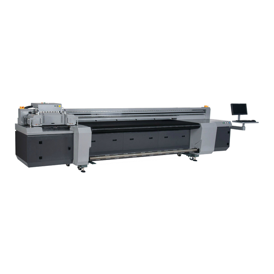
Introduction 1. Printer brief introduction The model of HT2500UV-C-HK4 Kyocera Hybrid UV inkjet printer is highly cost-effective equipment specially designed for commercial printing enterprises. Assembled with high-performance piezo heads that enables an output speed of up to 52 ㎡/h at the precision of 1200 x 1200 DPI. -
Page 9: Printer Configurations
Special negative pressure tank for keeping the pressure in the state of main power-off. More intuitive and user-friendly operating interface. With the ability to 24hoursX7days continuous running of commercial printing production. 4. Printer configurations Model HT2500UV Printhead type Kyocera high-performance drop-on-demand piezo heads Printhead array 2-4PCS Maximum resolution 1200*1200 DPI Printing speed... - Page 10 Nominal Voltage 400V Nominal Frequency 50Hz Steady state voltage 0,9 to 1,1 of nominal voltage Frequency 0,99 to 1,01 of nominal frequency continuously Harmonic distortion not exceeding 10 % of the total r.m.s. voltage between live conductors for the sum of the 2nd through to the 5th harmonic.
-
Page 11: Structure Diagrams
5. Structure Diagrams 5.1 Front view of the printer 1. Light Curtain Left 2. Emergency Stop Button Left 3. Carriage Assembly 4. Media Take up Roller 5. Electric Control Panel 6. Emergency Stop Button Right 7. Light Curtain Right 8. Computer Start-up Button... -
Page 12: Rear View Of The Printer
5.2 Rear view of the printer 1. Main Ink Tank Tray 2. Main Power Switch 3. Electric Box 4. Media Take-up Speed Switch 5. Media Take-up Direction Switch 6. Media Feeding Roller 7. Suction Control Panel... -
Page 13: Carriage Assembly
5.3 Carriage Assembly 1. Anti-crash bar Left 2. UV lamp housing Left 3. UV lamb housing Right 4. Anti-crash bar Right... -
Page 14: Electric Control Panel
5.4 Electric Control Panel 1. Media Take-up Direction Control Switch 2. Media Take-up Speed Control Switch 3. Power/Start Button 4. UV lamp Power Button Low Power 5. UV lamp Power Button High Power 6. Suction/Vacuum Button... -
Page 15: Suction Control Panel
5.5 Suction Control Panel 1. Suction Zone 4 Valve 2. Suction Zone 3 Valve 3. Suction Zone 2 Valve 4. Suction Zone 1 Valve 5. Print Zone Valve 6. Global Suction Volume Valve... -
Page 16: Electronic Box
5.6 Electronic box Relays Media feeding transformer AC Contactor 10. Carriage height motor driver Filter 11. 220V to 24V transformer 12. 15V Switch power supply Solid state relay 1 Solid state relay 2 13. 24V Switch power supply Solid state relay 3 14. -
Page 17: Labels And Logo On Printer
5.6 Labels and logo on printer 1,11... - Page 18 5,10...
-
Page 21: Printer Installation
Printer Installation 1. Loading and transporting The net weight of the printer is 1450kg Transportation and storage temperature: -20℃~60℃ The printer is a heavy-duty precision equipment of great value; thus the loading and transporting assignment must be assumed by qualified individuals, with a view to reduce the risks unexpected. -
Page 22: Working Environment
2. Working environment The limit distance of the moving part the machinery can reach is illustrated with dot-line box below. Set barriers for the area illustrated with black-line box below to prevent moving part doing damage to operators. Note that at least 500mm free area should be set for both front and rear side. Individual, clean, shadowy and dust-free workplace with associated ventilation Altitude: Below 1000 meter Constant humidity: 30%~70%RH(non-condensing) -
Page 23: Computer Configuration
4.5 Power input 3. Computer configuration Operating Motherboard Hard Disk Driver system PCIE port 500G Windows 7 64Bit supported Windows8 and Windows10 are not supported 4.Installation instructions 4.1 Check and acceptance Verify that all electronic units and mechanism are in normal state as soon as the printer is placed properly. -
Page 24: Leveling Adjustment
Load the assembly to the carriage. and fasten the screws The anti-crash attachment needs to be adjusted to some 0.5mm lower than the level of the bottom of the printhead tray when reassembling in the printer How to adjust the anti-crash attachment 1. -
Page 25: Software And Driver Installation
The printer should be properly ground wired. Diagrams below show the wiring method for various power input. 400VAC 50Hz 4.6 Software and driver installation Double click the corresponding installation package to start Select your own language... - Page 26 Select OS version. x64 for 64 bit windows Select the communication port.
- Page 27 Select the printer model . Select DPI.
- Page 28 Select rows.
- Page 29 Select UV lamp type Browse a path for TOPJet. It’s recommended to not choose system disk as installation folder. For example, “E:\”. Thus, the package will generate a folder named “E:\TOPJet” automatically.
- Page 30 Select additional task Confirm and install Wait for installation...
- Page 31 Install the initiations Click finish to continue...
- Page 32 Install the driver for PCIE card Accept...
- Page 33 Continue Finish. Normally we do not have to reboot computer after installation.
-
Page 34: Functional Tests
4.7 Functional tests Double-check the power supply, and test the following functions of the printer: Maximum and partial UV lamp power output activated properly Maximum and partial UV lamp power output activated properly X and Y directional moving properly Head height locating function running properly Print test OK 4.8 Printhead installation This step must be operated by qualified technicians with a view to avoid damage to... - Page 35 The connection of printhead cables can only be executed in the state of power-off. The pins of the cables must avoid to be dipped with any liquid and should never be bent. When dismantling the printhead, Wear rubber gloves goggle to protect yourself from the ink. Take all the assistant parts out and connect the connectors Finish Connecting as below Pay more attention to the heads and take the printhead out of the packing case...
- Page 36 Finish the connecting between sub tank to heads and fix the printhead...
-
Page 37: Filling Ink
Finish installing the printheads one by one See Appendix 5. Channel information of yocera head for connection of printhead cables 4.9 Filling ink The ink filling operation can only be executed when the ink lines and the connections of the cables are carefully double-checked after the printhead installation. Shutdown the spray function of the program and adjust the value to -1.5kPa, avoid the automatic protection of system when the negative pressure fluctuates in the ink filling operation process. -
Page 38: Printhead Calibration And Alignment
Wearing rubber gloves goggle to protect yourself from the ink Shutdown the spray function Turn off all the valves except the valves of the printhead, which needs to be exhausted and adjust the pressure to a value of -1.0kPa. Loosen the cap of the air exhaust tube of the printhead, and press the ink prime button till you see a constant ink stream comes out of the tube. -
Page 39: Vertical Alignment
②Vertical Adjusting Screw ③Horizontal Adjusting Screw 4.11.1 Vertical alignment Run the TOPJet program, click “Setup” to enter the “Printer Parameters setting” interface. Illustrated as below. Select the printhead vertical alignment in the drop-down-list of the alignment checking and run printing. Use the magnifier to observe the upper and lower parts of the small iron printed and sees whether the two parts merge into a complete one. -
Page 40: Horizontal Alignment
The lines of the two parts printed are There is one icon in the clockwise side. completely overlapped. Adjust the screw clockwise to make it Vertical calibration is good. aligned to the middle position with the exclamation mark How to adjust the Vertical Adjusting Screw 1. -
Page 41: Left/Right Heads Offset
H2, H3 and H4 are aligned to H1. H2 is not aligned to H1. Horizontal calibration is good. Adjust the screw clockwise to make it aligned to the left black head. How to adjust the Horizontal Adjusting Screw 1. Loosen the Head Fixing Screw 2. -
Page 42: Bi-Directional Offset Calibration
The left-side nozzles of the printhead (Cl) printed line align with the black line more perfectly in the icon with a figure of “-2”. Subtract 2 on the basis of the origin for C_l Aligned after adjusting offset parameters. Right Direction Offset using the same method with Left Direction Offset 4.11.4 Bi-directional Offset Calibration Select the “bi-directional offset”... -
Page 43: Stepping Calibration
The line overlaps the best at the position of figure +3 Plus 3 to the corresponding parameter (Here is the 1.0x speed, 18+3=21). 4.11.5 Stepping calibration Select the stepping checking print in the drop-down-list of calibration and alignment and get it output. Use the magnifier to observe and find a number indicates the best overlapping of the tiny lines. -
Page 44: Base Position Calibration
Adjust the parameter here. This method is not using a precise parameter calculating. Choose the most close one. 4.11.6 Base Position Calibration Select the “print base position” in the drop-down-list of calibration and alignment and get it output. Measure the distance between the datum checking print and the mechanical base point. - Page 45 Reset the value of the zero position in the layout option.
-
Page 46: Operating Instructions
Operating Instructions 1. Start-up and shutdown operation The user should go through the Safety Precautions chapter before the first-time operation. And all operations to be done by beginners must be executed under the instructions of professional technicians. For emergency stop press the any of the Emergency stop buttons. 1.1 Printer start-up operation Connect the power cable plugs to the wall socket. -
Page 47: Printer Shutdown Operation
Turn the main power breaker on. Start the computer. Turn on the four Emergency Stop Buttons on each corner of the printer. Then press the green “Power/Start” button for activation. Run the self-checking on the initial start of the printing system. Check if the reading value of the pressure is normal. -
Page 48: Printer Maintenance
Printer Maintenance 1. Periodic maintenance for printer parts With a view to keep the printer in good working conditions, operators should do the maintenance job periodically according to the following instructions. Clean the frame Clean the waste ink sink Clean the quartz glass of the UV lamp assembly Daily routine maintenance Clean the bottom of the printhead tray Check the negative pressure system... -
Page 49: Maintenance Of The Mechanical Parts
2. Maintenance of the mechanical parts Lubricate the moving mechanical parts with lithium grease monthly. X-directional Slide Way Y-directional Slide Way Mechanical parts Y-directional Screw Leads Z-directional Screw Lead Use the lever type grease gun to eject the lubricating grease into the slide block via the lubricating nipple assembly on the block. -
Page 50: Printhead Maintenance
4. Printhead maintenance* 4.1 Printhead daily routine maintenance Every day before or after work, take a nozzle checking print and see if there is any blockage. Execute priming or flushing immediately as soon as any blockage is observed. In the case, only one or two color are jetting during the printing process, a synchronize color bar printed with the image is strongly recommended. -
Page 51: Replacement Of Consumable Parts
5. Replacement of consumable parts 5.1 Replacement of ink pump When hearing three-consecutive buzz, Check and see if the ink pump malfunctions. A three-consecutive buzz may be caused by other malfunctions. You should verify the cause before parts replacing. Disconnect the plug of the ink pump cable and loosen the screws of the fixture. Remove the broken ink pump and remove the tubes connected to the pump. -
Page 52: Ink Refill
5.2 Ink refill When the hearing three-consecutive buzz, check and see if the ink is running out. A three-consecutive buzz may be caused by other malfunctions. You should verify the cause before refilling. Get a new bottle of ink and uncap it, put it nearby. Uncap the main ink tank which needs to be refilled. -
Page 53: Replacement Of Air Pump
The buzzer might generate three-consecutive buzz in the process of replacing. You need to reset the external device board after the replacement. 5.4 Replacement of air pump When hearing a single buzz during normal working hours, it means the main air pump has stopped working and the backup air pump is activated. -
Page 54: Replacement Of Ink/Air Tubes
5.5 Replacement of ink/air tubes The replacement must be replaced when any damage or spoil is found on certain tubes. Move the beam to the backward. Shutdown the spray and turn off the valves. Turn off the scram stop and disconnect the power cables of both air pumps. Disassemble the cover of the towline. -
Page 55: Troubleshooting
Troubleshooting 1. Buzz indications and troubleshooting There are six kinds of buzz alert programmed in the printer. Below is the list of indications and troubleshooting. Buzz type 1 BEEP Air pump issue Buzz indication Main air pumps stop working and the backup air pumps activated. When hearing the single-buzz alert Click the “Reset”... - Page 56 Buzz type 3 BEEPS Ink starvation Buzz indication One or more Sub Tank detect ink shortage for more than 15 seconds 1. Check if the ink of the main tank is running out. a) Refill it if so. 2. Check if the pump works properly by manual contact. a) Replace the ink pump if so.
- Page 57 Buzz type 5 BEEPS Ink backflow Ink backflow and triggers the sensor in Safe Tank. Possible causes: Buzz indication 1. Malfunctioning level sensor 2. Improper operation when disconnecting the ink tube. (Without the valve turned off or the pressure adjusted to -1.0kPa) 3.
-
Page 58: Pressure System Problems
2. Pressure system problems 2.1 Priming issue Ink does not come out from the nozzles when keep pressing the Prime Issue Description Button 1. Check if the ink valves to the corresponding ink is open. 2. Check if the sub-tank is empty (3 beeps alert). Troubleshooting 3. - Page 59 to reduce the possibility of deformation by strengthen the corresponding suction. There is a certain distance between the Head Height Sensor and the datum point. If the media is too small to be detected when placed near the datum point, you should put the media on the location for head height founder first.
-
Page 60: Carriage Moving Malfunction
4. Carriage moving malfunction 4.1 Carriage moving failure There are error messages displayed on the screen of the servo driver. Deal with the issue according to the corresponding information. Below is the list of information display on screen of the servo driver and the corresponding indication and troubleshooting. -
Page 61: Cache Problem
4.2 Cache problem Description The carriage pause too long at the two ends of the lead rail during the printing process. Troubleshooting Excessive image size or excessive file gross result in long data processing, and thus relate to printing data transmitting slowdown. Normally when processing some large image or a great number of images, adopt the mode of print after RIP. -
Page 62: Printing Quality Troubleshooting
6. Printing quality troubleshooting Abnormality Troubleshooting Check horizontal alignment Horizontal banding Check color calibration Check if the head height is right for the printing job, normally 2mm would be optimum. Unclear(blurred) printing Clean the nozzles surface Do the calibration again Color deviation Adjust the total ink limit by 10%-30%. -
Page 63: Appendix
Replace the shutter of UV lamp assembly monthly Replace the pump and filter half-year Replace the optical fiber half-year Reset the pressure indicator yearly Replace the quartz glass of UV lamp yearly Please contact with HANDTOP for more technical report when necessary. -
Page 64: Certifications
2. Certifications... -
Page 65: Company Information
3. Company information Company name: Shenzhen HANDTOP Tech Co., Ltd Legal Representative: Xiao Di Offiec Address: (Ciyu Factory, the third sub-factory) ,No 322, Yuanhu Rd, Zhangbei Industrial area.Xinlian Community,Longcheng street, Longgang district, Shenzhen, China. Tel: 86 755 29781665 / 29375551... -
Page 66: Rating Plate
4. Rating plate... -
Page 67: Tools And Properties
4. Tools and properties Tool/Spare parts name Description Needle Nose Pliers Cutting metal fuse Open or close the valve of the Sub Tank Ink valve wrench Adjusting the level of the printer when Adjustable spanner placed and future maintenance Loosen or fix the Allen screws for Allen wrench installation and future maintenance Loosen or fix screws for installation and... - Page 68 ii. CMYKLcLmWW-...
- Page 69 iii. CMYKVW- iv. CMYkWW-...
- Page 70 v. CMYKVVWW- vi. CMYKLcLm...
Need help?
Do you have a question about the HT2500UV and is the answer not in the manual?
Questions and answers