Advertisement
Quick Links
Advertisement

Summary of Contents for NAWON HTM-3788LDi
- Page 1 HTM-3788 LD...
- Page 2 ★ In order to order parts, please state Model No. and part No. in Part List pages • lease carefully read this manual before using the machine. • or more information, please contact us as shown the e-mail address below. ▶ E-MAIL : nawon@nawon.com, WEB SITE : www.nawon.com ▶ TEL : 82-31-942-1300 / FAX : 82-31-942-1305...
- Page 3 (1) Safety 1. Outline For seam sealing machine, a proper condition should be maintained in transportation, installation, and maintenance & repair. A supervisor should take good care of things in the processes above for safe and decent management of machine. Otherwise, a problem could occur.
- Page 4 □ All machine facility and parts in use should be included in "PART LIST." □ Proper support equipment and consumable goods are always reserved. □ When heavy parts are transported by a crane or forklift, safety check must be done in advance. Whether or not the parts are too heavy to transport should be checked and an operator watch out any worker under the cargo.
-
Page 6: Periodical Check
(3) Periodical Check Users should check maintenance & repair checklist in accordance with maintenance manual. (Daily, weekly, monthly) Description Period CHECKING Remove moisture in air filter DAILY Remove moisture in compressor Clean and check nozzle Regular check on electric parts WEEKLY Foot switch check Lubricant check... - Page 7 (4) Purpose of Machine and Installation 1) Most waterproof textiles are made of performance fabric which passes through air but blocks water. However, water may pass through needle holes which are created during sewing as shown in <Figure B> below. [Figure A] [Figure B] 2) In order to prevent water leak through the seam, this machine seals the seam...
-
Page 8: Installation
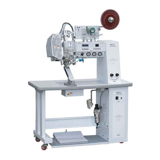
4) Installation - Place machine keeping 50cm distance from walls and lock the wheels with locking lever on the left wheel. 5) Air and Power Connection ⓐ Air pressure: 5kg/cm2 - 6kg/cm2 / Compressor capacity for 1 set: 3HP (NOTICE) Under low pressure, warning alarm may not go off and machine won’t be operated. - Page 9 (5) Preliminary Check before Operation 1) Check if air filter gauge pressure exceeds 5kg/cm2 (FT1 in Figure 1 below) Adjust the pressure to over 5kg/cm2 with adjusting lever If lower than 4kg/cm2, warning alert goes off and machine stops. 2) Check filter air tank and remove moisture if any .
- Page 10 (6) Pedal S/W Operation ⓐ UP / DOWN of Upper Roller (S/W “B”) 1) Whenever Pedal S/W B in [Figure 1] is stepped on, the upper roller moves up and down. [Figure 1] S/W “B” (Upper rollr part) S/W “A” (Nozzle part) ⓑ...
- Page 11 (7) Adjusting UP / DOWN Speed of Upper Roller Before adjusting the speed, ① check if air supply pressure in foot board filter exceeds 5kg/cm2. If it doesn’t, the adjusting job may not be done properly. (Gauge pressure of FT1 in Figure 3) ②...
- Page 12 (9) Upper Roller Stroke Control (Figure 5) Stroke needs to be adjusted depending on type of fabric and tape. * In an adjustment of stroke, the upper roller should face upward for easy adjustment. ① In case of thin fabric or tape, be careful not to damage the tape. ②...
- Page 13 (11) Nozzle Position Control Notices before adjusting nozzle - Make sure that temperature is low. - Make sure that power and air are off. Bolt H - After manually adjusting nozzle, do the precise adjustment with power and air on. [Figure 1] [Figure 2] Up/down adjust...
- Page 14 (12) Nozzle Angle Control (Figure 6) In order to adjust nozzle angle, make sure that the temperature is low. In case fabric is severely crushed (2-layer) or burnt (3-layer) when sealed with seam sealing tape, the nozzle angle should be adjusted. 1) Once the heat cools off, slightly loosen bolt F and tightly fasten bolt with (+) screw driver holding nozzle with spanner.
- Page 15 (14) Tape Setting 1) Install the tape in order as shown in [figure 1] ※ Watch out nozzle heat! 2) You can feed the tapes by using the Feed lever as Shown [Figure 2] 3) As [Figure 3], by using “tape width adjusting lever”, adjust the guide. ** Set the tape as shown in figure..
- Page 16 (15) Nozzle Heater Air Control Adjust the air by turning RG1 to the right or left and checking RG 1 gauge. Normally, 2 LAYER (PU, PVC) 1~1.2kg/cm2 / 3 LAYER 1.2~1.8kg/cm2 - NOTICE: If air gauge is below 0.8kg/cm2, temperature does not go up. [Figure 4] (16) Nozzle Heater Replacement Nozzle heater should be replaced when power is switched off.
- Page 17 (17) Replacement of Upper Roller Heater and Upper Rubber Roller 1) Replacement of Roller Heater Loosen bolt A and remove if from upper roller. Then, loosen and replace bolt B and C. Replacement of Upper Roller Loosen bolt A in [Figure 2], remove B plate, and then replace the roller.
- Page 18 NOTICE: ⓐ Because rubber roller spins under burning heat, it should be replaced with NAWON roller (there could be a problem in sealing) ⓑ A roller should be replaced while the temperature is off. ① A stain is observed on a tape after seam sealing.
- Page 19 ▶ Replacement of Thermometer (p 28, K401 T08, K402 T08-2) ① Temperature goes up and down greatly. (It could happen after data input is adjusted) ☞ Contact「NAWON」 ② The numbers on LCD change quickly. ③ Temperature doesn’t go up even though no problem is observed in nozzle heater sensor and heater.
- Page 20 ▶ Circuit Problem (p28, K404 W06-2) Check the followings: ① Check power 12V (W46-12) input voltage (Normal if "OK") ② Check input and output LED display when foot board is stepped on (Normal if "OK", bad circuit if "NO") ▶ A roller doesn’t spin. (a) Both upper roller and lower roller do not spin.
- Page 21 (19) Nozzle Replacement, Cleaning, Sensor Replacement ※Make sure that machine check is done when the heat cools off (lower than 40℃) ▷ Nozzle Replacement ① Unscrew bolt A, B, and C in Figure 1 and pull back cover D to the left. ②...
- Page 22 ▷ Sensor Replacement ① Unscrew bolt A, B, and C in Figure 1 and pull back cover D to the left. ② Unscrew bolt W and nut Y and replace sensor H. Be careful while unscrewing nut Y. Nut Y should not be unscrewed until the heat is completely gone.
- Page 23 (20) LCD Data description ⓐ LCD Disply description 1. MENU (M) ① Gently press the button. then, an arrow(←)mark display on the LCD & a setting mode is ready ② Then, use KNIFE (▲) & FEED (▼) to make a move ③...
- Page 24 ⓑ How to adjust and set nozzle temperature 1. SHIFT: Used to change SV (Set Value) Whenever the button is pressed, the unit changes to 1 / 10 / 100 degree(s) and flickers (UP/DOWN key is used to set the temperature) 2.
- Page 25 ⓒ HOW TO OPERATE THE LCD PANNEL * T/L (TAPE LENGTH) - [STANDARD FIGURE 45~50MM] - ADJUSTMENT OF THE TAPE'S LENGTH AFTER CUTTING TAPE. a. IF THE TAPE'S LENGTH IS TOO LONG, ADHENSION OF TAPE'S START IS NOT GOOD b. IF THE TAPE'S LENGTH IS TOO SHORT, THE TAPE CAN'T BE STABILIZED, BECAUSE OF NOZZLE AIR.
- Page 26 * ARM AUTO C/ARM AUTO RET (Arm Auto Control/ Arm Auto Return, Standard: 1.6 sec) This function controls the time that the upper roller slightly goes up and then, down when the seam sealing work is changed into the curve work from the straight line. If it is too long, the work efficiency will decrease and if it is too short, the accuracy can be down.
- Page 27 * FABRIC JAM on/off (Option) When the fabric is rolled up on the roller, the optical sensor senses it and the machine automatically stops. If this function is on, a letter, “J”, will appear at the bottom of LCD window. On/Off button is Extra 1 (F and J for the models of HTM-3877, 3888 and 5566).
- Page 28 (21) Whole Figure and Names...
-
Page 29: Electric Parts
(23) Electric Parts...
Need help?
Do you have a question about the HTM-3788LDi and is the answer not in the manual?
Questions and answers