Table of Contents
Advertisement
Quick Links
Advertisement
Table of Contents

Summary of Contents for Techno communications TK419
- Page 1 4G LTE GPS TRACKER User Manual v1.1 Model: TK419...
- Page 2 This page left intentionally blank...
-
Page 3: Table Of Contents
Contents: 1. Product Features ................................5 2. Components and Accessories ............................6 3. SIM Card Installation ..............................8 4. Device Installation ................................ 9 4.1 Install Device ................................9 4.2 Device wiring definition ............................9 4.3 Relay wiring ................................11 5. Power On / Off ................................12 5.1 Power On ................................ - Page 4 GPRS/WCDMA/LTE FDD network communication and the Internet. A real-time remote location and control of vehicles can be achieved through our powerful service platform. The TK419 also plays a significant role in logistics and cold chain, helping customers to achieve transparent management, reduce costs, ensure safety, and improve efficiency.
-
Page 5: Product Features
1. Product Features • Support GSM / WCDMA / LTE FDD. • Support GPS / Beidou / Glonass / Galileo /Qzss. A-GPS / LBS for aiding. • Data Uploaded by GPRS / WCDMA / LTE FDD regularly, check by Web / APP / SMS. •... -
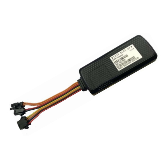
Page 6: Components And Accessories
2. Components and Accessories • Components Top (Needs to be mounted towards the sky) Bottom • Accessories (Optional) o Relay for remotely stopping engine. o SOS Button used for help. o External battery used for power supplier if backup is cut. o iButton can be used for interactive functions such as driver authorization. - Page 7 • Accessories (Continued) Please note that the device should be matched with accessories to realize these functions. Power Cable (Standard) Relay (Optional) iButton (Optional) SOS Button (Optional) External Battery (Optional)
-
Page 8: Sim Card Installation
3. SIM card Installation Open the packing case and check if device is okay and accessories are intact. You will need a full-sized SIM card for this device, please contact your dealer if you have any questions. Open SIM Card cover using a small blade screwdriver, being careful not to remove the waterproof O-ring located just underneath. -
Page 9: Device Installation
4. Device Installation 4.1 Install device 4.1.1 Please ensure the device is installed by an auto electrician otherwise you may void your warranty if wired incorrectly resulting in damage to the device. 4.1.2 Installation Notice • Hide device properly inside the car body to avoid damages and security from potential thieves. - Page 10 4.2.1 Power Cables and Interface The standard input voltage of the device is 9V-72VDC, using the supplied wiring harness, the Red wire needs to be connected to positive and the Black wire needs to be connected to negative/ground. Please connect the negative wire separately to ground and not to not to any other ground.
-
Page 11: Relay Wiring
4.3 Relay Wiring Relay wiring diagram shows how to wire the relay to control the fuel pump. 4.3.1 Connect the 86 port to the positive pole of the vehicle power (+12V / +24V). Connect the 85 port to the #4 wire (Yellow wire) of the device. 4.3.2 Remove the positive pole of the fuel pump and connect to the 87a pole of the relay and connect another wire from pole 30 of the relay to the fuel pump where you removed the positive wire. -
Page 12: Power On / Off
5. Power On / Off 5.1 Power On Power on: Insert a valid SIM card and wire all the cables, device will power on automatically. 5.2 LED Indicators The red LED flickers fast when device is searching for GSM/LTE network and will start to flicker intermittently when it has registered to the GSM/LTE network successfully. -
Page 13: Inquiry/Monitoring/Cut Engine
6. Inquiry/Monitoring/Cut Engine 6.1 Inquiry by Service Platform 6.1.1 Web Browser Platform Login to the GPS Service Platform (http://gps.technocomms.com.au) using your ID and password. If you do not know your login details, please contact us. 6.1.2 Smart Phone Application You can use a smart phone to check devices position. We have prepared for you the Android client, Apple client (IOS). -
Page 14: Device Alarms
7. Device Alarms 7.1 SOS Alarm To activate SOS alarm, the SOS button needs to be long pressed for 3 seconds. Note: SOS button must be installed (optional accessory) and SOS administrator number must be set. When SOS alarm occurs, device will send a SMS message to specified SOS administrator number. -
Page 15: Device Setting
8. Device Setting Please refer to Operation Commands on page 17. 9. Trouble shooting 9.1 Device is not connected to platform Device is never online on the position server when installed for the first time. Please check device: 1) Are power cables wired correctly? Pay attention to not connect them to controlling cables of vehicle. -
Page 16: Commands Receiving Abnormally
1) An auto electrician must be used to ensure correct installation into the vehicle and connection to the fuel pump. 2) Techno Communications will not be held responsible for damage to the vehicle as a result of misuse or incorrect installation. - Page 17 Operation Commands To use a command from below, type a new SMS message on your phone to the phone number of the device and have the format of the message as per below formats/examples. Function Format Example Note Saving Mode GPS,0# GPS,0# GPS,0#: GPS ALWAYS ON...
- Page 18 Manager MANAGER,Index,Number# MANAGER,1,0412345678# Manager number is used for Number cutting off power and fuel. Setting If the setup is successful, device will reply: SET MANAGER OK SET MANAGER ERROR Manger Manager,index? Manager,1? Device will reply: Number manager,1,0412345678 Inquiry Motion setting MOTION,sensitivity,timeou MOTION,2,5# Sensitivity range: 0-9 Timeout range: 0-60...
- Page 19 Restore power RELAY,0# RELAY,0# If setup successful, device reply: and fuel Relay disable OK Relay power RELAY? RELAY? Device will reply: and fuel status RELAY:DISABLE inquiry Latitude and WHERE? WHERE? Device will reply: Longitude Lon:E114.409238 inquiry Course:0.00 Speed:0.17KM/H Date Time:2011-09-13 20:21:20 Status inquiry STATUS# STATUS#...
Need help?
Do you have a question about the TK419 and is the answer not in the manual?
Questions and answers