Table of Contents
Advertisement
Quick Links
Cube WiFi Network Camera LC6760
DESCRIPTION OF THE SURFACE
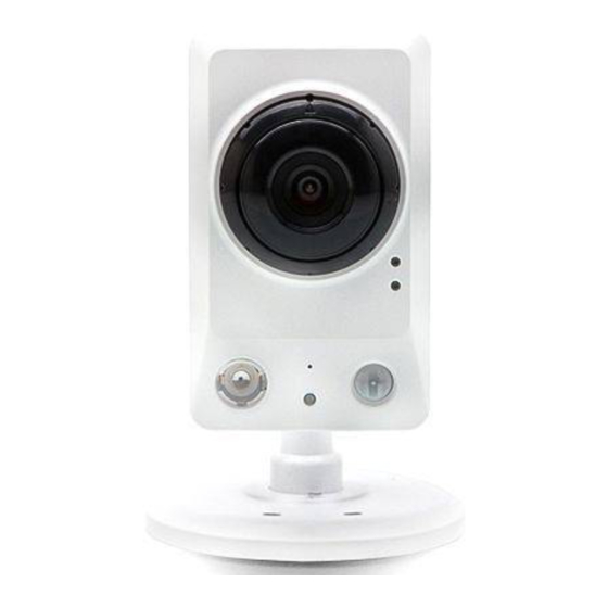
The Front View:
4
5
1.
Camera Len
s: Records video of the surrounding a
2.
Status LED: Indicates the camera's current status.
3.
WPS Status LED: Indicates the WPS connection status of the
camera. While connecting, the blue LED will flash.
4.
Microphone: Records audio from the surrounding area.
5.
Infrared LED: Used to illuminate the camera's field of view at
night.
6.
PIR Sensor: Passive Infrared sensor for motion detection.
7.
ICR Sensor: The IR‐Cut Removable sensor monitors lighting
conditions and switches between color and infrared accordingly.
Mount the Cube Camera
1. Place the mounting base and use a pencil to mark the holes. Drill two holes or screws where you marked. Fix the
mount base to the ceiling/wall with the screws.
2. Place the mounting base over the screw that is mounted on the wall. Make sure the base is locked. Place the base
cover on the base and screw the camera stem clockwise into the mounting base.
3.
Adjust the monitoring direction of the camera. Tighten the collar to lock camera in place.
Q
uick
The Rear View:
1
2
3
6
7
1.
rea.
2.
3.
4.
5.
6.
7.
8.
I
nstallation
DC-5V
2
3
4
RESET
8
Ethernet Port: This is a standard RJ‐45 connector for 10/100
Mbps Ethernet networks.
Power Connector: A DC 5V inlet that connects to an external
power supply.
DI/DO Connector: I/O connectors for connecting with external
devices.
Reset Button: Press and hold this button for 10 seconds to back
to its factory default settings.
WPS Button: Press this button, then push and hold another WPS
button on your router for 5 seconds to set up a wireless
connection automatically.
Micro SD Card Slot: Insert a Micro SD card as it local storage
including recorded image and video.
Speaker: Provides the camera's audio signal output.
Adjustment Ring: Tighten or loosen the adjustment ring to
adjust the camera's position.
G
uide
1
ETHERNET
5
6
WPS
7
1
Advertisement
Table of Contents

Summary of Contents for APPRO TECHNOLOGY LC--6760
- Page 1 uick nstallation uide Cube WiFi Network Camera LC6760 DESCRIPTION OF THE SURFACE The Rear View: The Front View: DC-5V ETHERNET RESET Ethernet Port: This is a standard RJ‐45 connector for 10/100 Mbps Ethernet networks. Camera Len s: Records video of the surrounding a rea. Power Connector: A DC 5V inlet that connects to an external power supply. Status LED: Indicates the camera's current status. DI/DO Connector: I/O connectors for connecting with external WPS Status LED: Indicates the WPS connection status of the devices. camera. While connecting, the blue LED will flash. Reset Button: Press and hold this button for 10 seconds to back Microphone: Records audio from the surrounding area. to its factory default settings. Infrared LED: Used to illuminate the camera's field of view at WPS Button: Press this button, then push and hold another WPS night. button on your router for 5 seconds to set up a wireless PIR Sensor: Passive Infrared sensor for motion detection. connection automatically. ICR Sensor: The IR‐Cut Removable sensor monitors lighting Micro SD Card Slot: Insert a Micro SD card as it local storage conditions and switches between color and infrared accordingly. including recorded image and video. ...
- Page 2 Hardware Installation-with an Ethernet cable To create an Ethernet connection: 1. Connect the power cable to the camera’s DC power jack. Then connect the power adapter to a power outlet. 2. Connect the Ethernet cable to the Ethernet port located on the rear of the camera. Then connect the other end into your router. 3. Confirm the correct network connection status. After the connection process is complete, the Status LED ( ② ) will turn solid green. Note Refer to the “Network Configuration” instructions of the User Manual, which is on the included CD‐ROM to connect your IP camera to a computer or a network with a RJ‐45 cable configuration for connections. Hardware Installation-with the WPS Push Button To c reate a WPS connection : 1. Power on your camera. 2. Press and hold the WPS button for about 5~6 seconds. The WPS status LED will flash blue ( ③ ). 3. Press the WPS button on your router within 60 seconds. The camera will automatically create a wireless connection to your router. While connecting, the blue WPS status LED ( ③ ) will flash. After the connection process is complete, the Status LED ( ②...
- Page 3 Install the Camera App- AppPro Please search for the AppPro app on the App Store or Google Play and download it to you mobile device. If you have a QR‐code scanning app, you can scan the corresponding code below to go straight to the app page. Add the Camera Tw methods to add a new camer a. 1. Scan QR code on the camera. . Manually type in the camera’s DeviceID and Password (default: 9999). Add the Camera-- QR Code Scan 1. Scan QR code of the camera: You can just scan the QR cod e to add a camera. 2. Select “+” (Add) on the screen to add the new camera. (1) To add camera by scanning QR code on the camera, please make sure that your camera has been reset to the factory settings. (2) QR‐code scan might not supported by some mobile device. Please visit your phone’s application store (the Google Play or App Store) and download a QR code reader/scanner app first. ...
- Page 4 St t to Monitor Android: Choose the camera on the camera list. Your mobile device will start connecting to your camera . iPhone: Choose the camera on the camera list. Your mobile device will start connecting to your camera. he Android Mobile Screen The iPhone Mobile Screen For the First Time Setup For the safety purpose, we suggest you create a new password in place to connect to the camera with the default password (9999). For the Android device, please select the to enter the camera configuration setting page. For the OS device, please select the to enter the camera function setting page. The Android Mobile Screen The iPhone Mobile Screen The CMS1030 (Central Management System) Software The CMS‐1030 software on the accompanying CD supports 32‐channel MPEG4, MJPEG, H.264 viewing, recording, scan IP function, authority and event management, and remote operations by LAN or Internet. The CMS‐1030 provides the most user‐friendly design with feature‐rich functions for intelligent surveillance systems. RMN0101370...
Need help?
Do you have a question about the LC--6760 and is the answer not in the manual?
Questions and answers