Advertisement
Quick Links
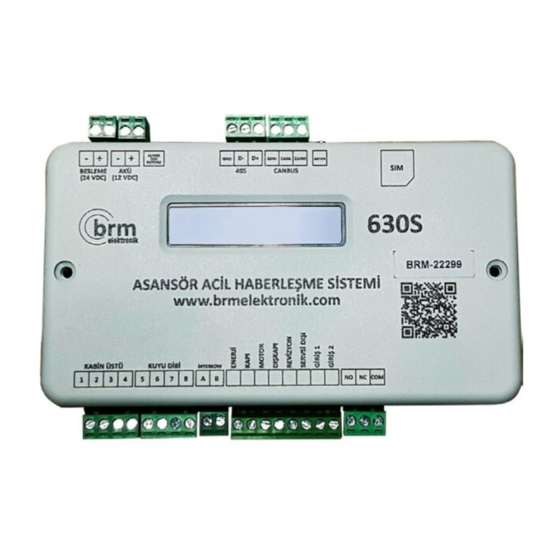
BRM 630 S
Elevator Emergency
Communication Set
Installation and
Installation and
User Manual
User Manual
Please read this manual carefully and
follow instructions exactly!
Technical Service
Communication
0555 109 57 40
Phone:
0850 220 28 81
1
Address
BAREMİR LTD. ŞTİ.
Ostim OSB Mahallesi
Alınteri Bulv. No:29/36
Yenimahalle / Ankara
www.brmelektronik.com
Online
Email :
brm@brmelektronik.com
Website:
www.brmelektronik.com
ENGLISH
MOBILE
MANUAL
Advertisement

Summary of Contents for brm elektronik 630S
- Page 1 BRM 630 S Elevator Emergency Communication Set Installation and Installation and User Manual User Manual Please read this manual carefully and ENGLISH follow instructions exactly! Technical Service Address Online Communication BAREMİR LTD. ŞTİ. Email : 0555 109 57 40 Ostim OSB Mahallesi brm@brmelektronik.com Phone: Alınteri Bulv.
- Page 2 DESCRIPTION OF BRM 630 S BRM-630 S is an emergency communication • It has a light system meeting requirements of the set which ensures bilateral communication for EN 81-70 or optionally relay outputs which can be elevators according to the standards 81-28 and connected with buttons.
- Page 3 Parts of BRM 630 S Follow these instructions during installation, maintenance and application stages. Any damage originating from any application types excluding in this manual will invalidate guaranty. In-Cab Module Main Module Cab Top Pit Bottom Engine Room Module Module ATTENTION It should be installed in easily accessible places that will not be affected by water and moisture.
- Page 4 Cab Top Module to Main Module Connection Type 1 Main Module Cab Top Mod. “BRM main module” can be connected with the “cab top module” in 3 different ways. ATTENTION: If the + 12V power input on the cabinet is taken directly from the revision battery, the BRM Device measures the power level of your revision battery...
- Page 5 Cab Top Module to Main Module Connection Type 2 Type 3 Main Module Cab Top Mod. Main Module Cab Top Mod. 1000 Connection to the common 1000 Connection with 4 cables line of the Panel with 3 cables www.brmelektronik.com...
- Page 6 Main Module to Pit Bottom Module Connection Type 1 Pit Bottom Mod. Main Module The Main Module and the Pit Bottom Module can be connected to each other in 3 different ways. The pit bottom module can be connected to the + 12V line in Pit Bottom +12V Kuyu Dibi the revision box.
- Page 7 Main Module to Pit Bottom Module Connection Type 2 Type 3 Main Module Pit Bottom Mod. Main Module Pit Bottom Mod. to the common 1000 line of the Panel Connection with 3 cables Connection with 4 cables www.brmelektronik.com...
- Page 8 In Cab Module to Cab Top Module Connection In Cab Mod. Cab Top Mod. www.brmelektronik.com...
- Page 9 In Cab Module to Cab Top Module Connection Cab Top Module Please contact BRM Technical Support in case an interconnect module is required. +90 555 109 57 40 Interconnect Module Useage Areas • Old type 530 N Cabin Module • ARGESET Cabin Module •...
- Page 10 In-Cab Alarm Button Connection Types ATTENTION Connection with (-): It is made with the in cab module that written v.02. If the module you have is not v.02, please turn the (-) end to (+) with relay. Floating connection Working with (-) In Cab Mod.
- Page 11 In-Cab Alarm Button Connection Types ATTENTION If there are external led connections on the buttons panel, the led connections can be made via BRM module. Working With (+) External LED Connection coming +12V when you press the button YELLOW LED GREEN LED www.brmelektronik.com...
- Page 12 GENEMEK Connection Schema www.brmelektronik.com...
- Page 13 MEGA 7 V Connection Schema www.brmelektronik.com...
- Page 14 Supply and Battery Connections Main Module - Battery Connection ATTENTION! Before connecting with 24 Volt DC Battery energy, measure the energy and make sure it is 24 V. If high voltage is present, it may burn your device. Main Module - Supply Connection Panel Main Supply +...
- Page 15 Filtration Connections HOW SMART FILTRATION WORKS? Main Module - Filtration Connections Intelligent filtering of BRM Devices; 1- Connecting the door, energy and motor ends 2- In panels with 81-28 filters, by connecting the energy and motor ends (IT MUST BE ACTIVATED WITH A SINGLE CABLE FILTERING FEATURE THROUGH BRM CLOUD).
- Page 16 Filtration Connections OUT OF SERVICE: This end is entered to Other Filtration Connections show that the lift is out of service. For informational purposes only. ENTRANCE 1: You can connect a module you want to monitor from the control panel and follow it by defining it through the BRM CLOUD system.
-
Page 17: Intercom Connection
Intercom Connection a- Connect terminals a and b ends of a handset that is compatible with the BRM Main Module - Intercom Connection 630 device to the ends of the Intercom socket with a suitable cable. b- When the alarm button is pressed for 8 seconds, the intercom device in the engine room is searched automatically. - Page 18 Plugging the Sim Card a. You can obtain a Postpaid line with a minimum of 100 Minutes - 200 SMS - 200 mb Internet package. b. SIM card must be the smallest size (NANO SIM). Cancel the PIN code of the SIM card. If the PIN code is not removed, the device will make a card error and the system will not work.
- Page 19 Signal Strength and Battery Check Signal Strength and Battery Check and Reading IMEI In BRM 630 devices, it means that there are 14 signal strength draws over 31 in the (RSSI) signal strength section (RSSI: 14) shown in the PICTURE BELOW. The signal strength of BRM630S models is between 1-31.
- Page 20 Information Entry / Opening with Password * REQIRED * ZORUNLU Factory default password is 123456. You can change it later. The setup will remain on for another 300 seconds with each successful SMS command. Kurulum:123456 Note: Do not leave spaces between characters in SMS messages you write.
-
Page 21: Changing Password
Changing Password / Information Entry * OPTIONAL Factory default password is 123456. Password changing command is “Sifre” After writing “Sifre” (without quotation marks) write current Sifre:123456 678102 password and leave a space then write new password. Finally push the send button. bırakmayınız Sifre:123456 678102 The password must consist of 6... -
Page 22: Adding Contacts
Information Entry / Adding Contacts * REQUIRED At this stage, 5 Tel2:+904441095740 phone numbers are entered sequentially. It starts by writing messages as Tel1:+905551095740 Tel1, Tel2, Tel3, Tel23:+903331095740 Tel4, Tel5. An international Tel1:+905551095740 code should be written at the beginning of the When the above SMS is sent to the Tel4:+907771095740 phone number. - Page 23 Adding Address Information / Information Entry * REQUIRED Start writing with “Adres”. There is only one “d” and “r” as you see. Adres: 55 Rue Gallieni, Up to 100 characters can be 93000 Bobigny, France written, including spaces. Adres: 55 Rue Gallieni, Do not use special characters! 93000 Bobigny, France You must use the English...
- Page 24 Information Entry / Adding Company Name * REQUIRED Start writing with “Firma” Up to 100 characters can be written, including spaces. Firma:Eagle Elevator Do not use special characters! You must use the English alphabet. Firma:Eagle Elevator When the above SMS is sent to the device, the screen right should appear.
-
Page 25: Changing The Menu Language
Other / Information Entry * OPTIONAL CHANGING THE MENU LANGUAGE ADDING OR REMOVING EXTERIOR DOORS TO THE FILTER Dil:1 DisKapi:1 Dil:1 DisKapi:1 This sms command must be entered in order to activate the language options. For activate the exterior door you must use “1”. For ”... - Page 26 Information Entry / Termination * REQUIRED, This section, where the processes are terminated, consists of 2 stages. FIRST STEP: SAVING SETTINGS SECOND STEP: COMMAND CLOSE Kaydet Bitir Kaydet Bitir Make sure to save, especially after entering the phone and address information. Write “Bitir”...
-
Page 27: Switching To Test Mode
Switching to Test Mode 1. The Alarm Termination button on the main module is pressed and released for 10 seconds like the left figure. TEST ON is displayed on the screen. 2. After 10 seconds after the cabin doors are closed, when the inside cabin alarm button is pressed for 20 seconds (This time can be... - Page 28 Switchingto Alarm Mode Switching to Test Mode Switching to Alarm Mode 3. While in test mode, SMS goes to the first registered phone number. • When pressed for 4. When the test mode is switched, the following max 3 seconds, it information can be read on the screen.
- Page 29 Alarm Termination After the recovery process takes place on BRM devices, alarm termination must be performed in order for the device and cloud system to record this process and reset the device. Alarm termination is done in 3 ways. When the alarm is terminated, a notification is sent to the first number registered in the system and to the BRM CLOUD system.
-
Page 30: Terms Of Guarantee
TERMS OF GUARANTEE • The BRM-630 branded products have 5 (five) year and parts to be changed. Repair can be carried out warranty for manufacturing defects provided in situ of the device, authorized service workplaces that principals, warnings and standards are or manufacturing site. - Page 31 TERMS OF GUARANTEE Industry and Technology and General Directorate • If the device is used in too humid or watery of Consumer and Competition Protection can be environment, applied. • Damages and breakdowns originating from low • The T.R. Ministry of Science, Industry and or high voltage, using groundless socket, faulty Technology and General Directorate of Consumer electric wiring.
- Page 32 WARRANTY DEED The T.R. Ministry of Science, Industry and Technology and General Directorate of Consumer and Competition Protection have granted permission to use this Warranty Deed pursuant to Law No. 4077 on Consumer Protection and the Communique on Principles of Applying Warranty Deed.
Need help?
Do you have a question about the 630S and is the answer not in the manual?
Questions and answers