
Related Manuals for EFORT ER12-4-2000


Summary of Contents for EFORT ER12-4-2000
- Page 1 ER12-4-2000 Mechanical Operation and Maintenance Manual for Industrial Robot EFORT INTELLIGENT EQUIPMENT CO.,LTD Hotline(Tel): 400-0528877...
- Page 3 This manual is only used as a guide for the normal operation of the product. During the use of the product, EFORT will not be liable for personal injury and property loss caused by other reasons except product defects. Our company...
-
Page 4: Table Of Contents
Mechanical Operation and Maintenance Manual for Industrial Robot ER12-4-2000 Content Chapter One Safety............................1 1.1 Instructions for Safe Use of Robots.....................1 1.1.1 Safety Precautions during Adjustment, Operation, Maintenance, etc........1 1.1.2 Safety Countermeasures of Robot Body.................. 3 1.2 Shift, Transfer, and Sale of Robots......................7 1.3 Abandonment of Robots........................ - Page 5 Mechanical Operation and Maintenance Manual for Industrial Robot ER12-4-2000 3.2.3 Ground Mounting........................21 3.2.4 Supporter Installation......................23 3.3 Installation Site and Environment..................... 23 3.4 Integrated Application Installation Interface..................23 Chapter Four Overhaul and Maintenance......................26 4.1 Preventive Maintenance........................26 4.1.1 Daily Inspection........................26 4.1.2 Quarterly Inspection.......................
-
Page 6: Chapter One Safety
Mechanical Operation and Maintenance Manual for Industrial Robot ER12-4-2000 Chapter One Safety 1.1 Instructions for Safe Use of Robots Before performing installation, operation, maintenance, and overhaul operations, please be sure to read this manual and other attached documents thoroughly and use this product correctly. Please fully grasp the equipment knowledge, safety information and all precautions before using this product. - Page 7 Mechanical Operation and Maintenance Manual for Industrial Robot ER12-4-2000 that it can stop safely even if an abnormality occurs. Even so, accidents caused by robots still occur from time to time. Most robot accidents are as follows: 1、The automatic operation was performed without confirming whether there is anyone in the robot's motion range.
-
Page 8: Safety Countermeasures Of Robot Body
Mechanical Operation and Maintenance Manual for Industrial Robot ER12-4-2000 When the robot is not in use, measures such as "press the emergency stop button" and "cut off the power" should be taken to prevent the robot from moving. Danger During the operation of the robot, please configure a monitor (the third party) who can immediately press the emergency stop button to monitor the safety status. - Page 9 Mechanical Operation and Maintenance Manual for Industrial Robot ER12-4-2000 conditions must be confirmed before operation. When installing the attached machine on the end effector and the mechanical arm, the size and quantity of screws specified in this book should be strictly observed, and the torque wrench should be used to tighten according to the specified torque.
- Page 10 Mechanical Operation and Maintenance Manual for Industrial Robot ER12-4-2000 Although electromagnetic interference is related to its type or intensity, there is no perfect countermeasure with current technology. When the robot is in operation or when the power is on, the operation precautions and regulations should be followed.
- Page 11 Mechanical Operation and Maintenance Manual for Industrial Robot ER12-4-2000 Operators should also maintain awareness of escape at all times during operations. It must be ensured that in an emergency, you can escape immediately. Attention Always pay attention to the actions of the robot, and do not work with your back to the robot.
-
Page 12: Shift, Transfer, And Sale Of Robots
Mechanical Operation and Maintenance Manual for Industrial Robot ER12-4-2000 When it is not necessary to make the robot move and operate, please turn off the power before performing the work. Attention After the teaching operation is completed, the robot movement should be manually checked at a low speed. - Page 13 Mechanical Operation and Maintenance Manual for Industrial Robot ER12-4-2000 Do not decompose, heat or incinerate the batteries used for the control device and robot body. Otherwise, fire, rupture and burning accidents will occur. Attention Do not disassemble the board and components of the control device before discarding it.
-
Page 14: Chapter Two Basic Description
Mechanical Operation and Maintenance Manual for Industrial Robot ER12-4-2000 Chapter Two Basic Description 2.1 Robot System Composition The industrial robot is composed of the following components, seen in Fig. 2-1: Robot body Control cabinet Teach pendant Connection (power supply) cables, etc. -
Page 15: Unpacking Check
Mechanical Operation and Maintenance Manual for Industrial Robot ER12-4-2000 2.2 Unpacking Check 1、Before unpacking, please confirm whether the outer packaging of the product is intact; 2、After unpacking, please confirm whether all parts of the robot are complete and whether the model is consistent with the order. - Page 16 Mechanical Operation and Maintenance Manual for Industrial Robot ER12-4-2000 Service hotline: Fig. 2-2 Robot Body Nameplate...
-
Page 17: Body Part Composition And Direction Identification Of Each Axis
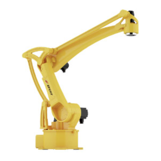
The names of the various components of the machine body and the identification of each axis direction are shown in Figure2-3: pipeline part the small arm part wrist part the big arm part the base part Fig. 2-3 Components of the Machine Body of ER12-4-2000... -
Page 18: Robot Axis Range Limit And Home Position
Mechanical Operation and Maintenance Manual for Industrial Robot ER12-4-2000 2.5 Robot Axis Range Limit and Home Position Each axis of the robot body has a home position and range limit. When the robot system is running normally, each axis of the robot is controlled to move within the allowable range. In addition, in order to ensure further safety, mechanical end stops are provided on some axes (seen Fig. -
Page 19: Robot Performance Parameters
Mechanical Operation and Maintenance Manual for Industrial Robot ER12-4-2000 2.6 Robot Performance Parameters 2.6.1 Table of Robot Performance Parameters Performance Parameter Table Model ER12-4-2000 Action type Articular type Control axis 4 Axis J1 axis 240°/s J2 axis 240°/s Maximum speed... -
Page 20: Robot Workspace
Mechanical Operation and Maintenance Manual for Industrial Robot ER12-4-2000 2.6.2 Robot Workspace P point The maximum workspace Fig2-5 Robot Range of Motion Note: The workspace shown in this figure is the maximum range of the P point in theory, which will change under the influence of installation mode in actual operation. -
Page 21: Allowable Value Of Wrist Payload
Mechanical Operation and Maintenance Manual for Industrial Robot ER12-4-2000 2.7 Allowable Value of Wrist Payload The installation payload at the front end of the robot wrist is affected by the allowable weight of the wrist, the allowable payload torque value, and the allowable moment of inertia. -
Page 22: Chapter Three Handling And Installation
Mechanical Operations and Maintenance Manual for Industrial Robot ER10-1600 Chapter Three Handling and Installation 3.1 Robot Handling 3.1.1 Handling Precautions The following are precautions for robot handling operations. Please work safely after fully understanding the following: The handling of robots and control devices must be carried out by qualified personnel for hook, lifting operation, forklift, etc. - Page 23 Mechanical Operations and Maintenance Manual for Industrial Robot ER12-4-2000 position J1 axis J2 axis J3 axis J4 axis Articular angle/° 2-Hexagon socket cap screws M6×16 Lift with 4 two-meter-long soft 2-Flat washer Grade C 6 cables bearing load of 500kg.
- Page 24 Mechanical Operations and Maintenance Manual for Industrial Robot ER12-4-2000 2-Hexagon socket cap screws M6×16 2-Flat washer Grade C 6 Hexagon bolt M12×60 2-Hexagon nut M12 Packing bracket Forklift pins 2×4-M10×20 screws Pins Fig. 3-2 Schematic Diagram of Handling When transporting, be sure to install a fixed fixture for transport!
-
Page 25: Robot Installation
Mechanical Operations and Maintenance Manual for Industrial Robot ER12-4-2000 3.2 Robot Installation 1、Set up safety fence Otherwise, accidents such as personal injury and equipment damage may occur. The robot should be placed in a position where the tool and the tip of work piece of the robot arm will not touch the safety fence even if the robot arm reaches the longest. -
Page 26: Ground Mounting
Mechanical Operations and Maintenance Manual for Industrial Robot ER12-4-2000 4-M16 penetration 4-ф18 through hole 4-M10 through hole 2-ф12 H7 pin hole and through Figure 3-3 Base Mounting Interface Dimensions 3.2.3 Ground Mounting Ground mounting requires the concrete foundation to be firm, the strength level and... - Page 27 Mechanical Operations and Maintenance Manual for Industrial Robot ER12-4-2000 is no loosening during operation, please fully fix and prevent loosening as shown in Figure 3-4 "Robot Installation Example". 4-M16×45 Chemical bolt components Specification requires M16 and above Plate thickness ≥30...
-
Page 28: Supporter Installation
Mechanical Operations and Maintenance Manual for Industrial Robot ER12-4-2000 Note: 2 GB/T 12×40 pins can be removed when accurate positioning of the robot is not required. Too long or too short screws for fixing the base of the robot will cause bad fixing accidents! The connection strength of chemical bolts depends on the strength of concrete. - Page 29 Mechanical Operations and Maintenance Manual for Industrial Robot ER12-4-2000 Robot external interface size As shown in the figure Remarks end load installation flange size Fig. 3-6 end load installation size dimensions of the external Fig. 3-7 external component installation component installed on the small...
- Page 30 Mechanical Operations and Maintenance Manual for Industrial Robot ER12-4-2000 Fig. 3-8 Dimensions of External Component Installed on the Wrist Body Ground terminal Peripheral Power cable aerial Encoder aerial plug plug interface interface Fig. 3-9 Dimensions of External Parts on Base...
-
Page 31: Chapter Four Overhaul And Maintenance
Mechanical Operations and Maintenance Manual for Industrial Robot ER12-4-2000 Chapter Four Overhaul and Maintenance Overhaul is divided into daily overhaul and regular overhaul. Inspectors must prepare overhaul plans and carry out overhaul. Please refer to the table below for overhaul items and overhaul periods. -
Page 32: Annual Inspection
Mechanical Operations and Maintenance Manual for Industrial Robot ER12-4-2000 screws 4.1.3 Annual Inspection Table 4-3 Annual Inspection Table Number Inspection items Inspection position cleaning and overhaul of various check whether there is a problem with the components component and deal with it... -
Page 33: Inspection Of Lubricant
Mechanical Operations and Maintenance Manual for Industrial Robot ER12-4-2000 To tighten and replace the screws, you must use a torque wrench to tighten with the correct torque, and then paint to fix it. In addition, it should be noted that bolts that are not loose should not be tightened with a torque higher than the required torque. -
Page 34: Change The Lubricant
Mechanical Operations and Maintenance Manual for Industrial Robot ER12-4-2000 4.4 Change the Lubricant 4.4.1 The Oil Supply Quantity of Lubricant Table 4-6 The fuel gauge of changing the lubricant Position Amount Name for the lubricant Remarks Rapid oiling will cause the pressure... - Page 35 Mechanical Operations and Maintenance Manual for Industrial Robot ER12-4-2000 and abnormal operation. Therefore, when performing lubrication operations, please observe the following: 1) Before performing the lubrication operation, open the oil drain port (remove the oil drain plug or screw plug).
-
Page 36: Release The Residual Pressure In Lubricating Oil Cavity
Mechanical Operations and Maintenance Manual for Industrial Robot ER12-4-2000 sealing tape gas source 4.4.4 Release the Residual Pressure in Lubricating Oil Cavity After the oil is supplied, in order to release the residual pressure in the lubrication tank, the robot should be properly operated. At this time, install a recovery bag under the lubricant inlet and outlet to avoid the spilled lubricating oil from scattering. -
Page 37: Home Position Calibration
Mechanical Operations and Maintenance Manual for Industrial Robot ER12-4-2000 Fig. 4-2 Maintenance and Use Areas Home Position Calibration Home position calibration refers to an operation performed to associate the angle of each robot axis with the encoder count value. The purpose of the home position calibration operation is to obtain the encoder count value corresponding to the home position. -
Page 38: Mechanical Home Position Calibration Of Each Axis
Mechanical Operations and Maintenance Manual for Industrial Robot ER12-4-2000 4.6.2 Mechanical Home Position Calibration of Each Axis When re-calibrating the mechanical home position of each axis of the robot, operate the robot in the jog mode to make each axis of the robot run to the home position alignment mark of each axis, and then enter the home position information interface of the robot teaching box to record the coordinates of each axis. - Page 39 Mechanical Operations and Maintenance Manual for Industrial Robot ER12-4-2000 Adjust the robot to the state of calibration (home position of each axis). To prevent danger, turn off the power supply, hydraulic pressure source and air pressure source connected to the robot.
-
Page 40: Appendix
Mechanical Operations and Maintenance Manual for Industrial Robot ER12-4-2000 Appendix A Table of Screw Tightening Torque Screw 12.9 grade Tightening torque (cast iron) Tightening torque (cast aluminum) 2±0.18 1.57±0.18 4.5±0.33 3.6±0.33 9±0.49 7.35±0.49 15.6±0.78 12.4±0.78 37.2±1.86 30.4±1.86 73.5±3.43 59.8±3.43 128.4±6.37 104±6.37... - Page 41 Mechanical Operations and Maintenance Manual for Industrial Robot ER12-4-2000 Lubricant MOLYWHITE RENO.00 2.5 kg Flat sealant THREEBOND 1110F THREEBOND 1374 Screw tightening agent...
- Page 42 Mechanical Operations and Maintenance Manual for Industrial Robot ER12-4-2000 Service hotline: +86-400-0528877 The rated power, specifications and external dimensions of this product are subject to change without prior notice. The technical data and illustrations are for reference only, and we reserve the right to change them.
Need help?
Do you have a question about the ER12-4-2000 and is the answer not in the manual?
Questions and answers