
Summary of Contents for Loadsensing LS-G6 Piconode
- Page 1 Loadsensing LS-G6 Piconode Configuring and operating the Loadsensing LS-G6 Piconode...
-
Page 2: Table Of Contents
Piconode Piconode overview Equipment Piconode installation Supports Powering the Piconode Piconode configuration Step 1: Connect DLog Android application Step 2: DLog main menu Step 3: Sensor wiring and set up Channel 1 for Full Wheatstone Bridge, Potentiometer/Ratiometric and Volt Single Ended Channel 2- Thermistor Channel 3 Pulse counter Step 4: Sensors data... -
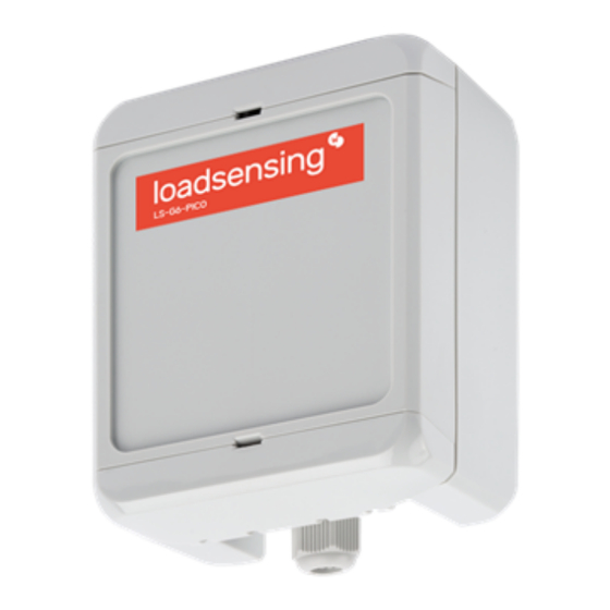
Page 3: Piconode Overview
Unlike other LS-G6 nodes, the antenna in a piconode is located internally in the casing upper cover. The coverage tests results prove that distances over five kilometres can be achieved in urban areas. https://www.worldsensing.com/product/loadsensing/ You can check the specifications of the piconode here: Equipment The Worldsensing LS-G6-Piconode is equipped with an internal antenna. -
Page 4: Powering The Piconode
● On a raised horizontal surface - same mounting brackets as above ● Inside a manhole (with a plastic or metallic cover) - no special accessories are available for this mounting type. Annex 10 LS-G6 Dataloggers installation on manholes for further detail Figure 1: Plan and section views of the mounting brackets (packs of four brackets and four screws) Figure 2: Lateral view of mounting brackets - vertical and horizontal positions Figure 3: Screw mounting dimensions... - Page 5 In order to initialise the piconode, the user should follow these steps: 1. Open the data logger (using a 2-mm flat-head screwdriver). The batteries should be inserted into the battery holder placed above the logical board (Figure 4). The internal antenna is internally attached to the cover and is connected to the main board though a cable - be careful not to snap the cable while opening the node Figure 4: The Piconode can be opened making use of a 2-mm screwdriver...
-
Page 6: Piconode Configuration
Figure 6: Unlike other LS-G6 nodes, there is no power switch in the Piconode Piconode configuration Ideally, this step of the process should be carried out in the same location in which the node is going to be installed. This way, you can perform an on-site radio coverage test. The node configuration process is done using the Worldsensing DLog app, which is compatible with any Android device equipped with OTG technology (Lollipop 5.1 sdk or higher is required). -
Page 7: Step 2: Dlog Main Menu
Figures 7, 8 and 9: in sequence, showing the first Dlog steps to set up a Piconode through Dlog app. Step 2: DLog main menu 1. Node info - Contains basic information about the node, such as version, ID, or temperature 2. -
Page 8: Step 3: Sensor Wiring And Set Up
Figures 10 and 11: Main configuration menu and Node configuration setting options, respectively 4. Factory Reset - this option resets the configuration parameters and removes all stored data. It is designed to allow the node to be used in different sites. We do not recommend using it for other purposes unless suggested by Worldsensing Technical Support 5. -
Page 9: Channel 1 For Full Wheatstone Bridge, Potentiometer/Ratiometric And Volt Single Ended
Figures 12 and 13: Three channels of the Piconode and Channel 1 options (sensor types), respectively Channel 1 for Full Wheatstone Bridge, Potentiometer/Ratiometric and Volt Single Ended... - Page 10 Figures 14, 15 and 16: Full Wheatstone bridge, Potentiometer/Ratiometric and Volt Single Ended sensors wiring diagram, respectively Full Wheatstone Bridge, Potentiometer/Ratiometric and Volt Single Ended are three types of signal output compatible with Piconodes, along with Thermistors and Pulse Counters, As shown in the above images, all three types of sensors are powered at 5 V dc through the Piconode.
-
Page 11: Channel 2- Thermistor
Channel 2- Thermistor Figures 18 and 19: Wiring diagram for a thermistor and available warm up times, respectively When connecting a thermistor, a warm-up time has to be entered (refer to the above explanation on warm-up time for Channel 1). -
Page 12: Channel 3 Pulse Counter
Channel 3 Pulse counter Figure 20: Wiring diagram for a pulse counter Sensors with potential-free (dry contact) pulses output are usually furnished with two cables, these two cables are interchangeable and have to be connected one to the PC (power connection) terminal and the other one to the AGND (grounding). -
Page 13: Step 4: Sensors Data
Piconode collecting data from the sensor or sensors it has connected but without having deployed a gateway to transfer the data. LS radio (Loadsensing radio) refers to having a node (Piconode in this case) and a gateway. - Page 14 ● MultiGW - Multi Gateway is to be selected for systems working with the multi gateway architecture (external dataserver) - currently the Piconode is not developed to work with the MultiGW new architecture After selecting the desired sampling rate and clicking on the Next button the setup is finished (figure 25). Figures 23 and 24: Two options under radio type and radio off settings for standalone Piconodes...
-
Page 15: Ls Radio
Figure 25: End of the test LS Radio This is the radio type to select when the Piconode is meant to send the data to a Gateway: frequency... - Page 16 Figure 26: LS Radio type Sampling Rate Choose the desired reading frequency from the drop-down menu (see Figure 27). The highest possible sampling rate is limited by the network size, and vice versa. Smaller networks can read up to every 30 seconds and frequency is progressively reduced on bigger networks.
- Page 17 Network Configuration - Network Size The network size (Figure 30) is the number of nodes (data loggers and Loadsensing wireless sensors). We strongly recommend initially setting it to the final number of nodes that the wireless network will have since this parameter determines the available sampling rates.
-
Page 18: Step 6: Radio Signal Coverage Test
Figures 30 and 31: Network size and network ID and password parameters, respectively Edit network ID and password This tab (Figure 31) needs to be activated (by swiping the button to the right) to enable radio communication between the nodes and the gateway. The user has to type the corresponding ID of the network and the password. Advanced options See the Radio specification chapter of the Gateway User Guide or Annex 01: LS G6 Gateway Radio Specifications v1.8 for more details on radio models and settings. - Page 19 ● Correct radio configuration of both the gateway and data logger (including matching region and ID/password configurations) ● Quality of the signal received by the gateway from the data logger Online Coverage Test By clicking the Next button, DLog will run an Online Coverage test. For the results of this test to be immediately displayed on the Android device, the gateway and the Android device must also be connected to the Internet.
-
Page 20: Step 7: Test Results Interpretation
If the gateway and/or the Android device are not connected to the Internet during the test, the Online Coverage test will fail and you will need to perform an Offline Coverage test. In this mode, however, the results of the test cannot be displayed on the Android device. - Page 21 Figures 35 and 36: Coverage test results (online test) expressed as spreading factor The SF is proportional to the distance between the data logger and gateway: higher SFs are capable of transmitting data at higher distances, while lower SFs reach lower distances. During the radio signal coverage test, the data logger sends five or ten data packages at SF7 to SF12.
- Page 22 Figure 37: Signal coverage test map from which the test results can be downloaded Figure 38: Download all tests of this network tool...
-
Page 23: Safely Closing The Piconode
When a new version of the app is available, DLog will display an automatic message asking the customer to upgrade it. To be able to have the latest Dlog version, the mobile phone or tablet in which the app is installed needs to have Internet, otherwise the customer should contact Loadsensing Technical Support for assistance. -
Page 24: Battery Lifespan
Battery lifespan This node can run on one or two battery cells and cannot be powered by an USB connector, that is to say, it cannot be powered by using an external power source. No Real Time Clock (RTC) battery is allocated in piconodes. As a result, anytime the battery or batteries are removed, you need to update the node’s time and date via Dlog app. -
Page 25: Data Acquisition And Storage
Notes: The above figures are estimated in lab conditions using 2 SAFT LSH 14 batteries with a nominal voltage of 3.6V (SAFT LSH 14 batteries product sheet). Type of sensors used for the calculation: 7.5 x 7.5Kohm potentiometer, , 3K thermistor and 300ohm wheatstone bridge strain gauge. -
Page 26: Pulse Counter Particularities - Engineering Units
Figures 44 and 45: Sensors data tool and settings to download data recorded for a certain period of time Pulse counter particularities - Engineering Units There are some particularities related to the pulse counter. This type of signal input implies data to be continuously stored, in a way that the value recorded when sampling is added up to the previous one. - Page 27 Steps to reset the node configuration via Gateway configuration On Networks – Node ID ● Click on the wheel icon located on the right side of the Last readings and Time series graphs panel as shown in the image below (Figure 46) Figure 46: By clicking on the wheel icon it is possible to reset the pulse value to zero ●...
- Page 28 Figure 47: Pulses minus an offset formula This formula will allow the pulses counting to be rest Enter the value to offset to zero (for example, if 23 pulses recorded, P0 shall be 23 to start counting over from zero value) Other formulae are captured below in Figures 48 and 49.
- Page 29 Figure 48: Pulse count formula The pulse count formula will allow you to get a cumulative pulses variation within a specific sampling period (hourly, daily, etc.)
- Page 30 Figure 49: Rainfall formula The Rainfall formula will allow you to get a cumulative pulses variation within a specific sampling period (hourly, daily, etc.) expressed in specific units, for example in mm which is equivalent to the litres of water poured per square metre of surface.
- Page 31 Regulatory notices FCC - Regulatory Notices Changes or modifications not expressly approved by the party responsible for compliance could void the user’s authority to operate the equipment. This device complies with part 15 of the FCC Rules. Operation is subject to the following two conditions: 1.
- Page 32 ISED - Regulatory Notices Changes or modifications not expressly approved by the party responsible for compliance could void the user’s authority to operate the equipment. This device complies with ISED license-exempt RSS(s). Operation is subject to the following two conditions: 1.
- Page 33 Avis de Conformité Réglementaire - ISED Les changements ou modifications non expressément approuvés par la partie responsable de la conformité peuvent annuler le droit de l'utilisateur à utiliser l'équipement. L’équipement est conforme aux CNR d’ISED applicables aux appareils radio exempts de licence. L’exploitation est autorisée aux deux conditions suivantes: 1.
Need help?
Do you have a question about the LS-G6 Piconode and is the answer not in the manual?
Questions and answers