
Summary of Contents for Baseband Technologies Stamp Module
- Page 1 Stamp-size Ultra Low-Power GPS Receiver Module User Guide Baseband Technologies Inc. Title: Stamp-size Ultra Low-Power GPS Receiver Module User Guide Rev. 1.0 Page 1...
-
Page 2: Table Of Contents
Description of the Stamp Module ..................................4 Overview ........................................4 Antenna ........................................4 Other Components and Connectors ................................4 Quick Start Guide For the Stamp Module ................................7 Overview ........................................7 Authorization procedure .................................... 7 3.2.1 Connect the Stamp Module ................................... 7 3.2.2... -
Page 3: Overview
GPS baseband processing firmware running on Maxim Integrated MAX32632 ARM Cortex-M4™ microcontroller (MCU). Scope This document is a User Guide for the Stamp Module. It describes how to configure and operate the module to evaluate the functionality and performance. Reference Documents Baseband Technologies Stamp Module product webpage: https://www.basebandtech.com/stamp... -
Page 4: Description Of The Stamp Module
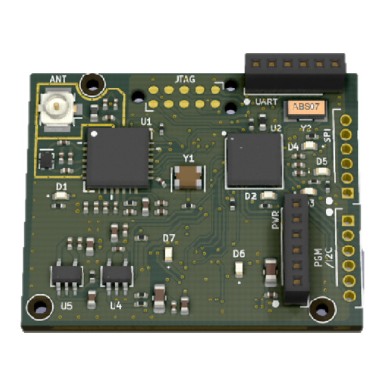
2 Description of the Stamp Module Overview This section describes the various connectors and basic functions of the GPS Stamp Module. A photograph of the Stamp Module is shown in Figure 1. Figure 1: Stamp Module (Left: Top-side, Right: Bottom-side) Antenna On the top-left side of the board, there is an U.FL type connector that is intended to connect to an... - Page 5 There are two 6-pin headers to interface with the Stamp Module. The UART header (J5) is intended to connect the Stamp Module to a UART port. During the initial testing phase, customers are advised to connect the Stamp Module to a PC using a FTDI or similar device with 3.3V I/O.
- Page 6 This is a 400 mAh, 3.7V Poly Lithium-Ion battery. The pin-out of the PWR header is: Pin-1: GND Pin-2: \RESET Pin-3: GND Pin-4: 5V Pin-5: PWRSW Pin-6: BAT Baseband Technologies Inc. Title: Stamp-size Ultra Low-Power GPS Receiver Module User Guide Rev 1.0 Page 6...
-
Page 7: Quick Start Guide For The Stamp Module
• If possible, disconnect all physical devices that are currently attached to the host PC (once section 3.2.2 is completed, you can reconnect those devices to the PC) • Connect the Stamp Module to the host PC via a FTDI device (LED D6 should light up followed by D4) Baseband Technologies Inc. -
Page 8: Identify The Com Port
Figure 3: Connecting the Stamp Module to the PC using a FTDI board 3.2.2 Identify the COM port • Download the Stamp Module utilities (utilities.zip) at the product webpage at https://www.basebandtech.com/stamp • Unzip the utilities to a folder of your choice (the example below created a folder named “RefDesign”... - Page 9 • Type “mode” to display the COM port that the Stamp Module is connected to (the example below shows the board is connected to COM6 of the host PC) Baseband Technologies Inc. Title: Stamp-size Ultra Low-Power GPS Receiver Module User Guide Rev 1.0...
-
Page 10: Retrieve The Stamp Module Id
3.2.3 Retrieve the Stamp Module ID • At the command prompt window, type “cls” to clear the screen • At the command prompt window, type “gpsconsole 6 getauthid” (replace the number 6 with the number corresponding to the COM port of your PC.) •... -
Page 11: Update Authcode
• If you have received your AUTHCODE via email, save the “authcode_XX-XX-XX- XX.gc” file to the utilities folder • To reconnect the Stamp Module, repeat the same procedure as outlined in sections 3.2.1 and 3.2.2. • At the command prompt window, type “cls” to clear the screen •... - Page 12 “ddddddddddddd” is a series of digits) • Using a text file editor, open the “authcode_XX-XX-XX-XX_ddddddddddddd.log” file to see the AUTHCODE and the expiration dates for the Stamp Module Baseband Technologies Inc. Title: Stamp-size Ultra Low-Power GPS Receiver Module User Guide Rev 1.0...
-
Page 13: Initialization Procedure
• To reconnect the Stamp Module, repeat the same procedure as outlined in section 3.2.1 3.3.2 Identify the COM port • To identify the port connected to the Stamp Module, repeat the same procedure as outlined in section 3.2.2 3.3.3 Update the Ephemeris •... - Page 14 • Type “gpsconsole 6 ephemeris” to inject the extended ephemeris to the Stamp Module Baseband Technologies Inc. Title: Stamp-size Ultra Low-Power GPS Receiver Module User Guide Rev 1.0 Page 14...
-
Page 15: Initialize The Stamp Module
The initialization procedure can be performed repeatedly without causing any harm to the Stamp Module. If unsure, repeat the initialization procedure. The initialization procedure usually takes seconds to complete but many factors could cause the initialization procedure to take up to 15 minutes to complete. To reduce the time required for the initialization process, use the @POS command to define initial position and uncertainty as described in section 4.1. - Page 16 • Close the text editor (Optional: You may wish to save any changes you made to “init.gc”) • With the Stamp Module connected, LED D4 will be illuminated to indicate that it is ready to accept commands. • Type “gpsconsole 6 init” to start the Initialization process.
- Page 17 Baseband Technologies Inc. Title: Stamp-size Ultra Low-Power GPS Receiver Module User Guide Rev 1.0 Page 17...
-
Page 18: Operating Procedure
• To reconnect the Stamp Module, repeat the same procedure as outlined in section 3.2.1 3.4.2 Identify the COM port • To identify the port connected to the Stamp Module, repeat the same procedure as outlined in section 3.2.2 3.4.3 Programming the Stamp Module •... - Page 19 • Type “gpsconsole 6 setup” to program the Stamp Module using the sample configurations defined in the setup.gc script (see section 4.1 for gpsconsole commands) Baseband Technologies Inc. Title: Stamp-size Ultra Low-Power GPS Receiver Module User Guide Rev 1.0 Page 19...
-
Page 20: Data Collection
3.4.4 Data collection Baseband Technologies Inc. Title: Stamp-size Ultra Low-Power GPS Receiver Module User Guide Rev 1.0 Page 20... -
Page 21: Data Capture And Data Parsing
“bti.pos” position file and (ii) extract each %ORS, %MS8, and %MS1 message appearing in the setup_20190513225447.log and convert them into individual binary files. Baseband Technologies Inc. Title: Stamp-size Ultra Low-Power GPS Receiver Module User Guide Rev 1.0 Page 21... -
Page 22: Advanced Operating Procedures
If the DTR pin is not available, see $RTS. Syntax: $DTR (HIGH | LOW | PULSE | AUTOSLEEP) Example: Baseband Technologies Inc. Title: Stamp-size Ultra Low-Power GPS Receiver Module User Guide Rev 1.0 Page 22... -
Page 23: Dynamics
LEVEL 0: 4ms LEVEL 1: 6ms LEVEL 2: 8ms LEVEL 3: 10ms LEVEL 4: 16ms LEVEL 5: 22ms LEVEL 6: 30ms Example: @LEVEL 6 Baseband Technologies Inc. Title: Stamp-size Ultra Low-Power GPS Receiver Module User Guide Rev 1.0 Page 23... -
Page 24: Output
“-“ will be disabled. -ALL will disable all output options. Examples: @OUTPUT ORS2LOG MS82LOG -MS12SPI @OUTPUT -ALL MS82LOG 4.1.9 $PAUSE Description: Baseband Technologies Inc. Title: Stamp-size Ultra Low-Power GPS Receiver Module User Guide Rev 1.0 Page 24... -
Page 25: Pos
This command should be used during power measurements to ensure the lowest power consumption. Syntax: @POWERSAVE (ENABLE | DISABLE) Baseband Technologies Inc. Title: Stamp-size Ultra Low-Power GPS Receiver Module User Guide Rev 1.0 Page 25... -
Page 26: Replay
@SETTINGS STORE # Write settings to flash @SETTINGS RESET # Reset current settings to factory default 4.1.15 @START Description: @START command initiates scheduled data collection Baseband Technologies Inc. Title: Stamp-size Ultra Low-Power GPS Receiver Module User Guide Rev 1.0 Page 26... -
Page 27: Stop
@UPDATE command sets how frequently the receiver will wake up to collect data Syntax: @UPDATE (frequency to wake receiver up for data collect in seconds) Example: @UPDATE 15 4.1.20 @VERSION Description: Baseband Technologies Inc. Title: Stamp-size Ultra Low-Power GPS Receiver Module User Guide Rev 1.0 Page 27... -
Page 28: Wake
(1.8V – 3.3V) or pulled low Syntax: @WAKE (ACTIVEHIGH | ACTIVELOW) Example: @WAKE ACTIVELOW # Keep receiver awake with the WAKE pin pulled low (default) Baseband Technologies Inc. Title: Stamp-size Ultra Low-Power GPS Receiver Module User Guide Rev 1.0 Page 28... -
Page 29: Data Processing For Modes 1 & 2
• Data Size: For .ors files only, select the number of milliseconds for the server to process. Baseband Technologies Inc. Title: Stamp-size Ultra Low-Power GPS Receiver Module User Guide Rev 1.0 Page 29... -
Page 30: Testing The Stamp Module
If you have a valid Google Maps API Key, enter it here. Testing the Stamp Module When evaluating the Stamp Module, customers are encouraged to develop a formal test plan to characterize the receiver performance. Test may include Time-to-First-Fix (TTFF), absolute and relative location accuracy (static and kinematic scenarios), acquisition and time to re-acquire, impact of multipath on absolute and relative accuracy, and power consumption etc. -
Page 31: Power Consumption Measurement
To accurately measure the board power consumption, all unnecessary components should be turned off. Refer to @POWERSAVE for details. Power the Stamp Module through the BAT pin using an external battery or a power supply set at 3.7V when performing power consumption measurements. - Page 32 3.2.1 and 3.2.2, except leave the 5V pin unconnected. • Connect the DTR pin on the FTDI board to the WAKE pin on the Stamp Module. If the FTDI board doesn’t have DTR then use RTS. The Stamp Module will go in to a hibernate state until gpsconsole is started.
- Page 33 • Type “gpsconsole 6 powermeasurement” to program the Stamp Module using the sample configurations defined in the powermeasurement.gc script (see section 4.1 for gpsconsole commands) • Confirm that LED D7 is turned off and that the message “Battery charging DISABLED” is displayed as shown in the example below.
-
Page 34: Tips
4.3.2 Tips The typical power consumption measurements illustrated in Table 1 includes all the necessary electronics components that make up the Stamp Module. More specifically, the measurements illustrated were based on the energy consumed by all the necessary components such as the (i) RFIC, (ii) TCXO, (iii) Active antenna, (iv) MCU and (v) power management IC. -
Page 35: Firmware Update
• To reconnect the Stamp Module, repeat the same procedure as outlined in section 3.2.1 4.4.3 Identify the COM port • To identify the port connected to the Stamp Module, repeat the same procedure as outlined in section 3.2.2 4.4.4 Erase the existing Firmware •... -
Page 36: Program The New Firmware
• Recycle power on the Stamp Module 4.4.5 Program the new Firmware • At the command prompt window, type “cls” to clear the screen • At the command prompt window, type “gpsconsole <port> loadkey_XX-XX-XX- XX.gc ” (do not reset power at this stage) ”... -
Page 37: Leds
4.5 LEDs Each of the 7 LEDs on the Stamp Module when used on its own or when combined with others has a specific meaning. The following describes meaning of the commonly seen LED configurations: • D1 (green): Active antenna detected and powered •... -
Page 38: Schematics
5 Schematics Download from https://www.basebandtech.com/wp-content/uploads/Stamp-Module-Schematic.pdf Baseband Technologies Inc. Title: Stamp-size Ultra Low-Power GPS Receiver Module User Guide Rev 1.0 Page 38... - Page 39 Download from https://www.basebandtech.com/wp-content/uploads/Stamp-Module-Schematic.pdf Baseband Technologies Inc. Title: Stamp-size Ultra Low-Power GPS Receiver Module User Guide Rev 1.0 Page 39...
- Page 40 Download from https://www.basebandtech.com/wp-content/uploads/Stamp-Module-Schematic.pdf Baseband Technologies Inc. Title: Stamp-size Ultra Low-Power GPS Receiver Module User Guide Rev 1.0 Page 40...
- Page 41 Download from https://www.basebandtech.com/wp-content/uploads/Stamp-Module-Schematic.pdf Baseband Technologies Inc. Title: Stamp-size Ultra Low-Power GPS Receiver Module User Guide Rev 1.0 Page 41...
Need help?
Do you have a question about the Stamp Module and is the answer not in the manual?
Questions and answers