
Summary of Contents for AstroLink 4 Pi
- Page 1 AstroLink 4 Pi manual - astrojolo.com AstroLink 4 Pi astrojolo.com @2021 Rev. 1.0...
-
Page 2: Main Features
AstroLink 4 Pi manual - astrojolo.com Main features: • Raspberry Pi 4 based astroimaging control center • dedicated AstroLink 4 Pi INDI driver • focuser motor control for Robofocus, Moonlite, or generic unipolar or bipolar stepper motor • up to 1/32 micro-stepping control with 2.0A maximum current and 1.4A maximum continuous hold current •... -
Page 3: Device Overview
Focusing motors control The focusing motor can be controlled with AstroLink 4 Pi device. The focusing stepper motor can be connected to the 6 pins RJ12 socket (see Figure 5). It supports 12V unipolar motors with gearboxes and bipolar motors at any microstepping resolution in a range of full step to 1/32. -
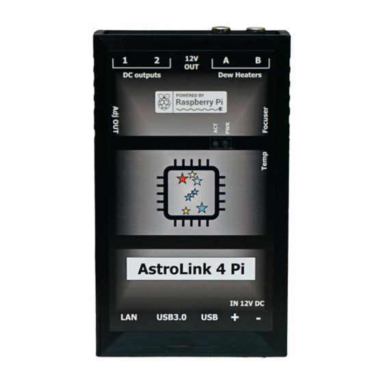
Page 4: External View
AstroLink 4 Pi manual - astrojolo.com External view Figure 1 - external views 1. LAN port 6. Regulated RCA outputs 2. USB3.0 ports 7. 12V DC output (non-switchable) 3. USB2.0 ports 8. Switchable 12V outputs 4. XT60 power input (12V DC) 9. -
Page 5: Hardware Setup
Figure 2 - enclosure screws Installing the Raspberry Pi module requires opening the AstroLink 4 Pi enclosure. You need to unscrew four out of eight screws at the device's sides. Please remove only bottom screws. Then remove enclosure top. After that, you need to unplug the cooling fan. -
Page 6: Setting Focusing Motor Current
Figure 4 - AstroLink 4 Pi interior If you can see the current regulation option in the Options tab of the AstroLink 4 Pi INDI driver, do not adjust the current using the potentiometer. It should be left at the factory default 0.4A, that is 0.2V. -
Page 7: Setting Regulated Output Voltage
AstroLink 4 Pi manual - astrojolo.com The default factory value is 0.4A – ready to use by unipolar Robofocus, Moonlite, or AstroLink motors, and safe for most of the bipolar stepper motors. The stepper motor socket pinout is presented in Figure 5. -
Page 8: Software Installation
The first step is to create a new hardware profile. Click plus icon next to the profile selector and fill it with all the equipment you have. As one of the Aux devices select AstroLink 4 Pi. Then click Save. -
Page 9: Main Control
Telescope device data (aperture and focal length). If the temperature sensor is connected to AstroLink 4 Pi device, then the Temperature section is present and the current temperature is displayed here. When temperature reading is available, also temperature compensation is possible. -
Page 10: Options
AstroLink 4 Pi manual - astrojolo.com Options Figure 8- Options tab Configuration – here you can load, save, reset or purge the INDI driver configuration. PWM cycle – that is the time in milliseconds that cycles regulated PWM outputs power. -
Page 11: Focuser
AstroLink 4 Pi manual - astrojolo.com Temperature coefficient – when the temperature sensor is available, temperature compensation may be performed. The number of steps per one degree of the temperature change should be entered into this field. Temperature compensate – enable or disable temperature compensation. The temperature compensation cycle is 30 seconds. -
Page 12: System
AstroLink 4 Pi manual - astrojolo.com System Figure 10- System tab This tab contains several read-only fields with some information about the system. System Ctrl section allows to reboot or turn off the operating system, but to use these buttons some additional configuration of sudo is required, so these operations are allowed without a password. -
Page 13: Outputs
There are three DC 12V outputs in the device. One is permanent, and two are switchable and can be controlled in this panel. There are also two RCA sockets in the AstroLink 4 Pi that can be used for powering dew cap heaters. These sockets provide PWM regulation with a long cycle time (the period can be set in the Options tab) in the range of 0 to 100%. -
Page 14: Temperature Compensation
AstroLink 4 Pi manual - astrojolo.com Temperature compensation Temperature compensation in AstroLink 4 Pi is implemented linearly. So there is only one parameter that describes how temperature affects the focus point. It is not a perfect approach, however, its accuracy is good enough for most amateur setups. -
Page 15: Ground Loops
In this scenario, a negative voltage is supplied to the camera also in two ways. The first one is the main power cable between the camera and AstroLink. The second loop is from 5V output in AstroLink to the USB hub and then with the USB cable to the camera. -
Page 16: Troubleshooting
WiFi network, then it will start as a failover with its WiFi hotspot: SSID astroberry, password astroberry, IP 10.42.0.1. If all above fails, then switch off the home router, so there is no WiFi around, and restart AstroLink 4 Pi. After about two minutes it should be astroberry WiFi available, where you can connect. -
Page 17: Table Of Contents
AstroLink 4 Pi manual - astrojolo.com Table of contents Main features: ............................2 Technical data ............................2 Device overview ............................3 System and hardware requirements ....................3 PWM outputs ............................3 Switchable 12V DC outputs ......................... 3 Focusing motors control ........................3 Permanent 12V DC output ........................
Need help?
Do you have a question about the 4 Pi and is the answer not in the manual?
Questions and answers