
Summary of Contents for Spectra 1964 C610
- Page 1 Model C610 Operation Manual Contact Information: 860 West Riverdale Road Suite D6 Riverdale, UT 84405 801-605-8849 9:00 AM – 5:00 PM MST WWW.SPECTRA1964.COM 6/1/2019...
-
Page 2: Table Of Contents
TABLE OF CONTENTS UNPACKING AND INSPECTION……………………………..…………………………………………3 INTRODUCTION………………………………………………………..…………………………………3 SPECIFICATIONS…………………………………………………..……………………………………..4 QUICK START GUIDE……………………………………………………………………………………5 MODES OF OPERATION………………………………………….……………………………………...8 Principal of Operation Normal Linear Amplification Peak Limiting Only Compression and Limiting Simultaneously Compression Only Limiting and Compression with Additional Fixed Amplitude Protection CONTROL AND MONITOR FUNCTIONS…………………………………………………………….12 Constant Threshold Operating Advantage No “De-Ess”... -
Page 3: Unpacking And Inspection
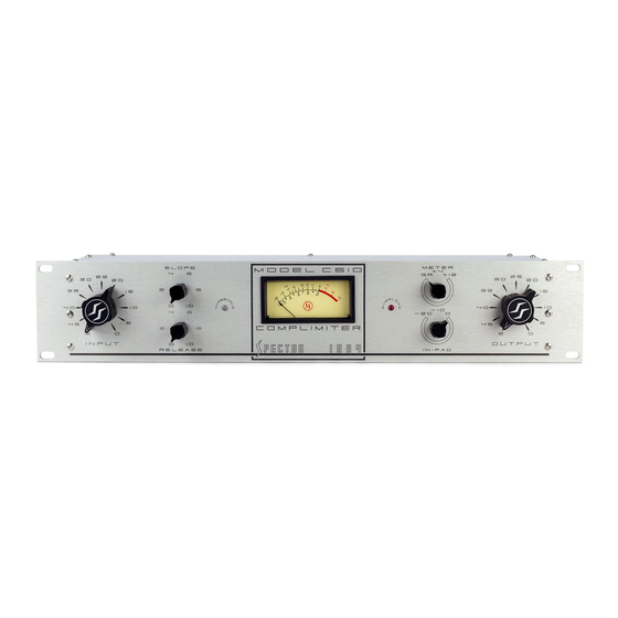
Depending on the program content, the Model C610 “COMPLIMITER” will accept an input signal from -50 dBu to -40 dBu just prior to beginning compression, as well as standard line level input signal. -
Page 4: Specifications
SPECIFICATIONS Input Impedance……………………..………………………………………………….2.4 kOhms nominal Output Impedance………………………..………..Approximately 120 ohms (1kHz), floating Output Loading………………………..…………...600 ohms to Infinity, balanced or unbalanced Maximum Gain……………………………………………..………………………………..56 dB Input Level………………………………..…………………………Typically -50 dBu to +10 dBu Threshold Attack Level………………………………………..…………………………-40 dBu Output Level………………………..…………………………………Typically +4 dBu or +8 dBu Signal-to-Noise Ratio……………………...…..Not less that 80 dB below +4 dBu output with -40 dBu input (threshold), 20 Hz to 20 kHz, unweighted. -
Page 5: Quick Start Guide
PROPER SETUP OF THIS CONTROL WILL ALLOW FOR CONSISTENT AND REPEATABLE PERFORMANCE The C610 compressor circuit is designed to operate levels of -40dBu or greater. The input level control allows for adjustment to attain -40dBu level. As gain is increased beyond the -40dBu input level, resulting compression follows incrementally. The amount of input level compression may be readily viewed on the C610 meter by selecting the gain reduction setting,(GR), located on the front panel. - Page 6 The C610 Complimiter has a gain of 56dB. Of the total, approximately 40dB of gain is provided by the second, 101 amplifier module. The sole purpose of the 101 module is to make-up gain for the C610. The output knob of the C610 controls the 101 module gain. If the input gain is set at -40dBu as described earlier, then the amount of undistorted gain available is 56dB with 1.1-1 compression.
- Page 7 (5.) Release Control The release control knob affects the signal release time after initial signal compression. Maximum release time, marked "10" on the front panel, will slowly restore gain to the original level. Long release times are often used for multiple source program material, main program channel material, mastering, or very slow source material from a single source. (6.) Slope Control The slope control provides the widest range of compression/limiting ratios available, from 1.1:1 to 100:1.
-
Page 8: Modes Of Operation
Please note that the C610 is a professional low impedance device. The C610 is transformer balanced for the input and output sections of the device. For unbalanced operation, combine pin 1 (shield), with pin 3, signed minus (-). Pin 2 is signal plus (+). -
Page 9: Peak Limiting Only
Microphone and Line Level Settings Control settings: For low signal levels (e.g. Microphone, etc.), no attenuation of the input signal is required and the threshold attack LED will occasionally flash whenever input levels are above threshold. For higher signal levels (e.g. Line, etc.), it is preferable to operate above the point of threshold and thus maximize the signal-to-noise ratio of the system. The slope control is set to approximately normal linear amplification (“10” slope control setting = fully clockwise), the release control setting is not critical and may be set at maximum time. The input level control is adjusted so the threshold attack LED is continually illuminated. For either of these two conditions, adjust the output level control to obtain the level required. Typical Application: This mode provides amplification for input signal levels below the -40 dBu threshold attack level, such as when normal microphone output levels, (-50dBu), are terminated directly to the Model C610. For higher level input signals, setting the slope control to approximately normal linear amplification has the practical equivalent of switching the Model C610 out of the circuit. Peak Limiting Only For all levels of the input signal waveform where peak signals are above threshold, and average level is below threshold, peak limiting occurs. Peak waveforms or transients, by definition, are high amplitude, short time-base, and are beyond the audible range, (20 kHz). Thus, the independent limiting function will attack, instantaneously, to provide complete peak overload protection. The limiting curve approximately follows the compression curve and, a continuously variable limiting curve is obtainable. For positive amplitude protection, a flat compression slope provides a flat limiting protection line. Control Settings: Increase the input level control until the threshold attack LED occasionally begins to flash, indicating peaks are beginning to cross threshold. The control setting will approximately represent the maximum amplitude of the peak material for this audio program selection. The maximum amount of peak limiting will occur just prior to the point where the VU meter begins to indicate gain reduction. The slope control is set for minimum, (flat), slope of the limiting, (and compression), curve (fully clockwise). Since compression is not being activated, the release control setting is not critical and would be set for maximum release time, (fully clockwise). Adjust the output level control to obtain the level required. Typical Application: Maximum Vu output without affecting dynamic range is obtained without maximum peak limiting. With no compression of audio program source material, no peak program material will be transferred through the Model C610, thus allowing improved audio level. As a result, increased headroom will be realized without associated “peak overload”, (typically 10dB). In addition, an improvement in signal to noise ratio will be achieved in proportion to the increase in signal level. -
Page 10: Compression And Limiting Simultaneously
Compression and Limiting Simultaneously This mode of operation occurs when the average level continually alternates above and below the constant threshold attack level. When the audio program waveform initially crosses threshold, the limiter will attack and hold until the compression function takes over. The cycle will repeat each time the average level crosses the threshold. The compression slope does not change the threshold attack level or the threshold indication. The release time will determine how long the function will hold. Control Settings: Increase the input level control until the Vu meter begins to indicate compression. The threshold attack LED indicator will be illuminated continuously since the average signal level will now be above threshold. The amount of additional compression is dependant upon the input level control setting. When the release control is set for the shortest release time, maximum average level will be obtained with an increase in audio level and distortion. Longer release time will provide the smoothest action with minimum audio level changes, minimum distortion and average level slightly lower than the maximum. Adjust the output level control to obtain the level required. Typical Application: This mode is used whenever a small or intermediate amount of compression is desired. Compression Only When the average level of the input signal to the compressor/limiter is continually above the threshold attack level, this mode occurs. Control Settings: Increase the input level control until the Vu meter continually reads compression and the threshold lamp is continually illuminated. Generally, longer release times should be used. Typical Application: Wherever a large amount of compression is required, operate in this mode. Limiting and Compression with Additional Output Limiting/Broadcast Application This mode is the same as the previous “Compression and Limiting Simultaneously” mode, except that additional amplitude protection at a fixed level is provided by driving the output amplifier to maximum output, (peak clipping). The system provides “limiting-on-limiting,” which assures maximum power output or maximum percent modulation. When utilized in this manner, an external pad after the Model C610 is needed to reduce the higher output level to line level. The red overload lamp indicator is set to illuminate for output amplifier signals of approximately +17 dBu, well in advance of the actual output amplifier limiting of +18 dBu or greater. Under normal circumstances, this is the preferred operation. However, additional precise laboratory lamp indication at the point of output amplifier limiting may be preferred. Calibration of the overload light for this function is available at a nominal charge from the factory. - Page 11 Control Settings: Set the controls in the same manner as described in the previous “Compression and Limiting Simultaneously” mode except that the output level control should be set so the red overload lamp begins to flash. Thus, a final fixed amplitude protection line is provided to prevent subsequent overload distortion, over-modulation, etc. Typical Applications: This mode is particularly applicable to broadcast applications where a maximum percentage of modulation is required. A resistance in series, (e.g. 600 ohms, 1000 ohms potentiometer, etc.) where signal output is sufficient to pad the signal positive down to standard +8 dBm broadcast line (e.g. 600 telephone lines etc.) level. This mode may be used for any application where maximum level is to be obtained without crossing above a maximum amplitude protection line.
-
Page 12: Control And Monitor Functions
CONTROL AND MONITOR FUNCTIONS Constant Threshold Operating Advantages The constant threshold attack level provides a significant operating advantage by eliminating the need to continually reset the input level for each new variation of compression ratio. Thus, comparison analysis on simplified “A-B” basis is possible and the selection of the desired slope of the compression curve is easier, more accurately determined, and requires less time. No “De-Ess” Roll-Off The need for “de-ess” or “de-emphasis” has been eliminated through the advanced design dual function, independent compression and limiting of the Model C610. Conventional single function analog compressor/limiters are not capable of reacting in time to protect against higher frequency sibilant sounds without markedly sacrificing the performance of audio program material. Considerable engineering design effort was required to develop a sophisticated dual function system. “De-ess” or “de- emphasis” controls frequencies irrespective of whether or not transients or sibilant peaks are present. The professional audio engineer is no longer in control of the final program output from such competitive conventional units due to either “roll-off” of all high frequencies to avoid sibilant distortion from only a few high frequencies, or tolerate sibilant distortion from high frequency peak overload. THE FREQUENCY RESPONSE OF THE MODEL C610 DOES NOT CHANGE UNDER NORMAL LINEAR AMPLIFICATION, LIMITING AND/OR COMPRESSION. Input and Output Level Controls THE INPUT CONTROL REGULATES THE AMOUNT OF COMPRESSION/LIMITING DESIRED. The system is capable of receiving input signals 30 dB above the constant threshold attack level without degradation in performance. The output control regulates the system output level and is located after the compression/limiting plug-in module and before the final amplifier plug-in module. Continuously variable control of the input and output signal levels is provided to allow any value of attenuation. The Vu meter may be used to monitor accurately this attenuation. Slope (Compression/Limiting Ratio) Control The Model C610 provides both: 1. The widest range of compression/limiting ratios – from approximately 1.1:1 (approaching linear amplification) to 100:1 (flat slope). 2. Continuously variable selection of compression ratios – which may be changed during use to obtain any desired slope of the compression curve without producing transients, pops, clicks, etc., or changing the threshold attack level. For inputs up to the point of threshold (-40 dBu), the compressor/limiter provides 20 dB of gain. Thereafter, the output is dependant upon the compression/limiting ratio selected. The unit... - Page 13 When the slope control is set to the maximum compression/limiting ratio of approximately 100 to 1 (“0” slope control setting = fully counterclockwise), the compression/limiting curve is flat. Hence, the maximum amplitude output is held to a constant -20 dBu for any input level up to 30 dB above threshold. This extremely flat slope is very useful whenever a positive protection line limit is required. Conversely, when the slope control is set to the minimum compression/limiting ratio of approximately 1.1:1 (“10” slope control setting = fully clockwise), the slope of the compression curve approaches the linear amplification curve. The Model C610 approximates the operation of a normal linear amplifier, and provides approximately 20 dB of gain for input above threshold. For typical intermediate slope control settings, refer to Figure 1, Compression Curve Slope vs. Slope Control Settings. For slope control settings of approximately “5” (50% open), a signal input increase of 15 dB above threshold, will increase the output approximately 7.5 dB, which is a 2:1 compression/limiting ratio.
-
Page 14: Release Control
Release Control The continuously variable release time control regulates only the compressor release function. Distortion is a function of release time and the amount of compression/limiting. Maximum release time (“10” on the panel, fully clockwise) will slowly restore gain back to its original level. For lowest distortion and smoothest response, the release time should be at least an order of magnitude greater than the time of one cycle of the lowest frequency to be processed. Longer release time settings are often used for multiple source program material, main program channel material, mastering, or very slow music from a single source. Minimum settings of release time, (“0” on the panel, fully counterclockwise), will quickly restore gain back to its original level. For maximum average level below a fixed amplitude output, the release control should be set at the shortest time; however, distortion and level change variations will be greater. Minimum release times are often used for single source, vocal or solo source material with low background noise and/or low background program material. As the background level increases, the quick release to normal level, (short release time), will be audibly detectible as a rapid change in background program level. Figure 2, Actual Release Time, (90% signal recovery) vs. Release Control Settings, illustrates the wide degree of continuous release time variation available. In addition, all the release times may be reduced if required. Please consult the factory for adjustment procedures. FIGURE 2 ACTUAL RELEASE TIME VS. RELEASE CONTROL SETTINGS... -
Page 15: Overload Indicator Lamp
In summary, the optimum release control setting for maximum level below fixed amplitude will be the shortest possible release time commensurate with the minimal amount of distortion and/or level changes. Judicious listening and selection of release times for various program selections is recommended, using this information as a guide Threshold Attack Indicator LED The Vu meter needle mechanism cannot respond to instantaneous peak limiting of the Model C610 system on high amplitude, short time base transients. A Vu meter is capable of indicating longer time base signal. When illuminated, the white threshold attack LED indicates that audio signal (e.g. transients, peak program material, etc.) have crossed the constant -40 dBu threshold attack level of the Model C610. The frequency of the illumination, (e.g. flash, flashing, steady, etc.) from the LED indicator gives the user an approximate representation of the peak limiting taking place, without the task of monitoring with an auxiliary oscilloscope. If the input signal remains above threshold for a longer time, the threshold attack indicator LED will remain illuminated and the Vu meter, (meter switch set to “GR”), will indicate the amount of GAIN REDUCTION, (compression), that will automatically occur. Overload Indicator LED The red overload indicator LED will illuminate whenever excessive input or output signal level overload, (+16 dBu), occurs. In some applications it is particularly desirable to utilize the overload indicator LED as a guide to obtaining additional limiting with the output of the Model C610. Meter Switch A three position rotary switch is provided for selection of the Vu metering between gain reduction and two output levels. When set to “GR” the Vu meter indicates the amount of gain reduction, (compression). When set to “+4” or “+8” and the Vu meter is monitoring the output signal level, 0 Vu on the Vu meter corresponds to +4 dBu or +8 dBu, respectively. Input Pad Selectable 10/20 dB input pad. -
Page 16: Warranty
EQUIPMENT WARRANTY The following warranty is effective for all Spectra 1964, LLC (Manufacturer) products. Spectra 1964 warrants that this product is free of defects in both materials and workmanship. Should any part of this product be defective, the Manufacturer agrees at its option, to: A. Repair or replace with a like new replacement any defective part free of charge (except transportation charges) for a period of one year for all products. This warranty period begins on the date the end user is invoiced for the product, provided the end user provides proof of purchase that demonstrates that the product is still within the warranty period and returns the product within the warranty period to Spectra 1964, LLC, according to the Product Return and Repair Policy set forth below. All inbound shipping costs are the responsibility of the end user; Spectra 1964, LLC will cover all outbound shipping costs. Product Return and Repair Policy Return to Manufacturer 1. An RMA (return merchandise authorization) number must be obtained by the end user from Spectra 1964, LLC. 2. The user must return the product to Spectra 1964, LLC with proof of purchase (showing purchase date) for a warranty claim, and display the RMA number on the outside of the shipping package. THIS WARRANTY IS VOID IF: • The product has been damaged by negligence, accident, act of God, or mishandling, or has not been operated in accordance with the procedures described in the operating and technical instructions, or • The product has been altered or repaired by other than the Manufacturer or an authorized service representative of the Manufacturer; or • Adaptations or accessories other than those manufactured or provided by the Manufacturer have been made attached to the product which, in the determination of the Manufacturer, shall have affected the performance, safety or reliability of the product; or • The product’s original serial number has been modified or removed. NO OTHER WARRANTY, EXPRESSED OR IMPLIED, INCLUDING WARRANTIES OF MERCHANTABILITY OR FITNESS FOR ANY PARTICULAR USE, APPLIES TO THE PRODUCT. MANUFACTURER’S MAXIMUM LIABILITY HEREUNDER SHALL BE THE AMOUNT PAID BY THE END USER FOR THE PRODUCT. No person or entity authorized to assume any obligation or other liability in connection with the products. No action, regardless of form, arising out of or relating to the product or this warranty, may be brought by end user more than one (1) year after the cause of action has accrued. Manufacturer shall not be liable for punitive, consequential, or incidental damages, expenses, or loss of revenue or property, inconvenience, or interruption in operation experienced by the end user due to a malfunction in the purchased product. No warranty service performed on any product shall extend the applicable warranty period. In case of unsatisfactory operation, the end user shall promptly notify the Manufacturer at the address set forth below in writing or call (801) 605-8849 giving full particulars as to the defects or unsatisfactory operation. Upon receipt of such notice, the Manufacturer will give instructions respecting the shipment of product, or such other matters as it elects to honor this... - Page 17 warranty as above provided. This warranty does not cover damage to the product during shipping and the Manufacturer assumes no responsibility for such damage. All shipping costs shall be paid by the customer. This warranty extends only to the original end user and in not assignable or transferable. This warranty is governed by the laws of the State of Utah, without regard to the conflicts of interest’s provisions thereof. Spectra 1964, LLC 860 West Riverdale Road Suite D6 Riverdale, UT 84405 801-605-8849 9:00 AM – 5:00 PM MST...
Need help?
Do you have a question about the C610 and is the answer not in the manual?
Questions and answers