
Related Manuals for KEHUI T-710


Summary of Contents for KEHUI T-710
- Page 1 T-710 Intelligent Cable Identifier User Manual Kehui International Ltd. 2 Centrus, Mead Lane, Hertford Hertfordshire, SG13 7GX United Kingdom Phone: (+44) 1920 358990 Fax: (+44) 1920 358991 Website: http://kehui.com...
- Page 2 Legal Notices The copyright of this material belongs to Kehui International Ltd. No company or individual may extract, copy or translate in any way without the written permission of the copyright owner. Copyright infringement will be investigated. This product complies with the design requirements for environmental protection and personal safety.
- Page 3 Thank you for purchasing the T-710 intelligent cable identification device. The T-710 is a light-weight, high power device for accurately identifying a specific cable from a group of adjacent cables and is a complementary product to the Kehui range of cable fault location equipment.
-
Page 4: Table Of Contents
TRANSPORTATION AND STORAGE ..............27 TRANSPORTATION CONSIDERATIONS ............27 STORAGE CONDITIONS AND PRECAUTIONS ........... 27 UNPACKING INSPECTION, MAINTENANCE AND WARRANTY ......27 INITIAL CHECKS ....................27 MAINTENANCE ....................27 WARRANTY...................... 28 PACKING LIST: ....................29 T-710 | Version 1.0 | 4... -
Page 5: Safety Instructions
Indicates that this is a useful guideline based on field practice. Use of accessories: Kehui’s spare parts must always be used to ensure the safe and reliable use of this instrument. Using accessories made by other companies will make any warranty null and void. -
Page 6: General Description
General Description General T-710 is a high-performance cable identification system, composed of a signal transmitter T-710T and receiver T-710R. It is used to accurately identify the target cable among multiple cables. It is suitable for live and uncharged cables, including three-core cables with armour. -
Page 7: Specification
HMI: 800 x 480 pixels LCD • Battery: Two 18650, 3.7V 6.8Ah • Dimensions: 220 x 125 x 55mm • Weight 0.9kg • Operating temperature: -10 C to +40 • Relative humidity: 5 – 90% T-710 | Version 1.0 | 7... -
Page 8: Device Composition And Accessories
Figure 2.2 Transmitter overview 2.4.2 Receiver ① Output port ⑤ Power on/off ② LCD display ⑥ Calibration key ③ Charging port ⑦ Output frequency decrease ④ Charging socket ⑧ Output frequency increase Figure 2.3 Receiver overview T-710 | Version 1.0 | 8... -
Page 9: Signal Transmission Methods
T-710 | Version 1.0 | 9... -
Page 10: Wiring And Operation For Direct Connection
• There should be no other cables or pipelines between the earthing pin and the target cable, otherwise the transmission signal will be induced on them, which will cause interference. T-710 | Version 1.0 | 10... - Page 11 If the voltage on the cable exceeds the limit (50V), the voltage detection interface will display a warning sign (Figure 3.3c), and there will be no output thus protecting the instrument from damage. Figure 3.3c Overvoltage warning T-710 | Version 1.0 | 11...
-
Page 12: Wiring And Operation Of Clamp Coupling Method
Both ends of the cable sheath should be earthed as the coupling current will decrease as earthing resistance increases. The clamp coupling method can only be used where both ends are earthed and the sheath is unbroken. T-710 | Version 1.0 | 12... - Page 13 Step 3: After completing the wiring, when the transmitter is turned on, it will automatically detect the connected test line and lock it in the clamp output mode. T-710 | Version 1.0 | 13...
-
Page 14: Connection Modes For Cable Identification
The ability to identify a particular cable is an important aspect of cable maintenance. Cables are often composed of several core conductors with metal armour. Different wiring methods produce different electromagnetic fields and require detection approaches described in the following section. T-710 | Version 1.0 | 14... -
Page 15: Out Of Service Cable Wiring Method
The remote end must always be earthed using an earthing pin which should be inserted into the ground as far as possible from the earth grid, otherwise earth current return may flow on other cables, adversely affecting the measurement. T-710 | Version 1.0 | 15... - Page 16 There is no shielding in this connection, so the signal generated in the ground is strong and the signal characteristics are relatively clear. T-710 | Version 1.0 | 16...
- Page 17 (there is a phase difference between the two). Depending on site conditions, the total effective current may account for up to ten percent of the total injected current. T-710 | Version 1.0 | 17...
-
Page 18: Live Cable Wring Method
The clamp is equivalent to a primary winding of a transformer, and the cable sheath to earth loop is equivalent to a single-turn secondary of the transformer. T-710 | Version 1.0 | 18... -
Page 19: Transmission Frequency Selection In Cable Detection
Therefore, it is recommended to use 640Hz when transmitting signals for the detection of long-distance cables. 640Hz and 1280Hz are composite frequency signals, allowing the receiver to readily identify them. T-710 | Version 1.0 | 19... -
Page 20: Smart Cable Identification
Figure 5.1 Flexible sensor connection Introduction to the receiver interface After power on, the receiver automatically recognises the connected accessories and sets it to sensor receiving mode. The interface is as follows: Figure 5.2 Receiver interface T-710 | Version 1.0 | 20... -
Page 21: Calibration
This will be the reference for following measurement. After setting the reference, the data should be saved. If the instrument is switched off, the data will be saved. When identifying other cables, the reference must be reset for the new target cable. T-710 | Version 1.0 | 21... -
Page 22: Cable Identification
Core conductor-earth connection method basic operation Figure 5.4 Intelligent sensor recognition process using the core conductor – earth connection T-710 | Version 1.0 | 22... - Page 23 I, with the phase near 180°, leading to recognition of incorrect cables. Figure 5.5: Results for three parallel cables with core conductor earth connection T-710 | Version 1.0 | 23...
- Page 24 Figure 5.6: Results for three parallel cables with core conductor earth connection T-710 | Version 1.0 | 24...
- Page 25 • Recheck the wiring • Repeat the calibration process • Ensure that the sensor is connected with its arrow in the right direction T-710 | Version 1.0 | 25...
-
Page 26: Power Frequency Current Measurement
AC supply and leakage current, etc. The flexible sensor coil on the T-710 allows non-contact measurement of the current and has no exposed metal parts. It is safe, fast and convenient due to its small size, light weight, reliability, high measurement accuracy and bandwidth response frequency. -
Page 27: Transportation And Storage
(non-bleach) household cleaner. As a basic principle, do not let moisture into the Receiver charging port; if the surface of any of the instruments becomes wet, dry it with a soft cloth. T-710 | Version 1.0 | 27... -
Page 28: Warranty
The instrument is guaranteed for one year from delivery for any problems arising from product quality issues. If problems occur due to improper use or are beyond the warranty period, contact Kehui International or one of its approved distributors for assistance. (info@kehui.com) Repairs attempted without the express permission of Kehui will invalidate the warranty and may lead to further damage to the equipment. -
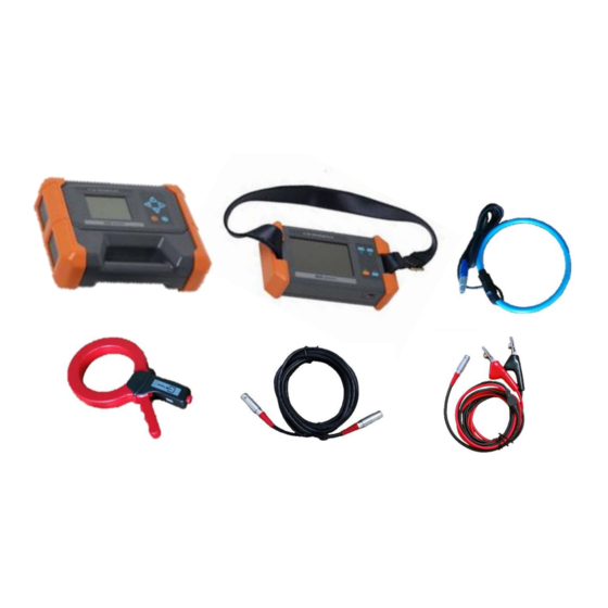
Page 29: Packing List
Packing list: Description Appearance Quantity. T-710 Transmitter T-710 Receiver Transmitter direct connection cable Transmitter accessory cable Transmitter clamp coupler Receiver sensor Earthing rod Transmitter power cable Receiver charger Carry case Manual T-710 | Version 1.0 | 29...
Need help?
Do you have a question about the T-710 and is the answer not in the manual?
Questions and answers