
Summary of Contents for Hydraram HSS Series
- Page 1 STEEL SHEAR - HSS SERIES Operation and maintenance manual Hydraram B.V. Meander 7, 9231DB, Surhuisterveen Holland Tel : +31 512 365 981 - info@hydraram.com www.hydraram.com Certified company 11-2021...
-
Page 3: Table Of Contents
Table of contents 1. Introduction 5. Installation 1.1. Purpose of the user and maintenance instruction manual 1 5.1. Moving and handling 1.2. Safekeeping of the instruction manual 5.2. Storage 1.3. Updating the instruction manual 5.3. Coupling check 1.4. Who is this manual intended for? 5.4. Mounting the attachment on the operating machine 1.5. -
Page 4: Introduction
The manual must be stored correctly and kept where it may be readily consulted when using the attachment with the operating machine. The company Hydraram may not be held liable in the following cases: •... -
Page 5: Safekeeping Of The Instruction Manual
1.2. Safekeeping of the instruction manual The manual must be stored carefully and kept together with the attachment whenever the latter changes hands throughout its working life. The manual will last longer if it is handled carefully with clean hands and not placed on dirty surfaces. - Page 6 OPERATOR AREA STATUS OF THE OPERATING MACHINE The area where the operator must work during The status of the operating machine includes normal use of the attachment. its operating mode, for example, automatic, jog, stopped, etc., the condition of the safety devices DANGER ZONE on the operating machine, such as safety devices An area inside and/or near the attachment where...
-
Page 7: Copyright
1.6. Copyright The copyright of this manual is the property of Hydraram. This manual is intended for use by operating and maintenance personnel. It contains instructions and technical diagrams that may not be copied, in whole or in part, distributed or examined by unauthorised persons for competitive purposes or divulged to any other third party. -
Page 8: General Information
Each attachment is identified by a CE plate indelibly marked with all the relevant machine information Always provide this information when contacting Hydraram or the customer service centre. The plate is secured to the attachment in a protected position where it is easy to read. This position may vary depending on the model. -
Page 9: Set-Up Procedures To Be Carried Out By Customer Technician
Hydaram guarantees that all products are free from material or manufacturing defects. Under the terms of this warranty, Hydraram’s responsibilities are limited to the repair or replacement with a similar part at the company’s plant, on condition that the product is returned within 8 days of the date on which the defect is detected, and provided the defect is correctly identified by photographs or the product is returned with all shipping expenses prepaid. - Page 10 Hydraram, the company is unable to intervene promptly in the aftermath of breakdown or fault condition, the customer shall be responsible for any further deterioration or damages resulting from the continued use of the Hydraram products. Any such additional damage is not included in the terms of the warranty.
-
Page 11: Safety
3. Safety 3.1. General precautions Operator safety is one of the manufacturer’s main concerns. When designing and manufacturing a new attachment, we attempt to foresee all possible danger situations and, naturally, to adopt suitable safety measures, paying particular attention to operations that are especially hazardous. The manufacturer may not be held liable for the consequences of any failure to adhere to the safety and accident prevention instructions set out in this manual. - Page 12 It is, however, extremely important to adhere scrupulously to the following instructions: • It is strictly forbidden to operate the attachment with the fixed protection panels removed; • It is strictly forbidden to inhibit or bypass the safety devices installed on the attachment; •...
-
Page 13: Intended Use
Make sure that there are no objects between the parts of the attachment. After any maintenance work, check that there are no objects remaining between moving parts. To guarantee maximum safety when transporting the attachment, it is FORBIDDEN: • To tamper with any part of the attachment; •... -
Page 14: Safety Indications Relating To Use Of The Attachment
3.4. Safety indications relating to use of the attachment Overhead working may result in falling debris or blocks of material. Make sure that the machine the attachment is installed on has the necessary protections for performing this type of work and that the cab has falling object protective structures (FOPS). •... -
Page 15: Operator's Position
IMPORTANT! Hydraram declines all liability for any accidents, injuries to personnel or damage to property resulting from the failure to adhere to the general safety instructions and the standards set out in this document. -
Page 16: Accident Prevention Plates And Labels
Operator Areas: These are the areas in which the operator must work during normal operation of the attachment. The “operator areas” are considered potentially dangerous areas. In these areas, which are indicated on the following diagram, the operator should pay the maximum attention while working to protect the well-being of persons close by;... -
Page 17: Safety Pictograms
Symbol Description Symbol Description “Greasing points” “Oil input” Indicates the points to be lubricated. Power/rotation oil inlet. “Oil return” “Rotation direction” Power/rotation oil outlet Direction in which the attachment must rotate “Drainage” “Lifting points” Overflow point for excess oil. Use the indicated points when handling and moving the attachment 3.8. Safety pictograms In the manual various pictogram may be used to indicate warnings regarding DANGER, PROHIBITION and... -
Page 18: Residual Risks
3.9. Residual risks A residual risk is a hazard that cannot be completely eliminated through design and protective techniques or a potential hazard that is not obvious. Hazard: crushing/cutting limbs Hazard: ejected oil Possibility/location of hazard Possibility/location of hazard When assembling disassembling or performing When assembling/disassembling or performing maintenance on the attachment there is a risk of maintenance on the hydraulic components of the... -
Page 19: Lighting
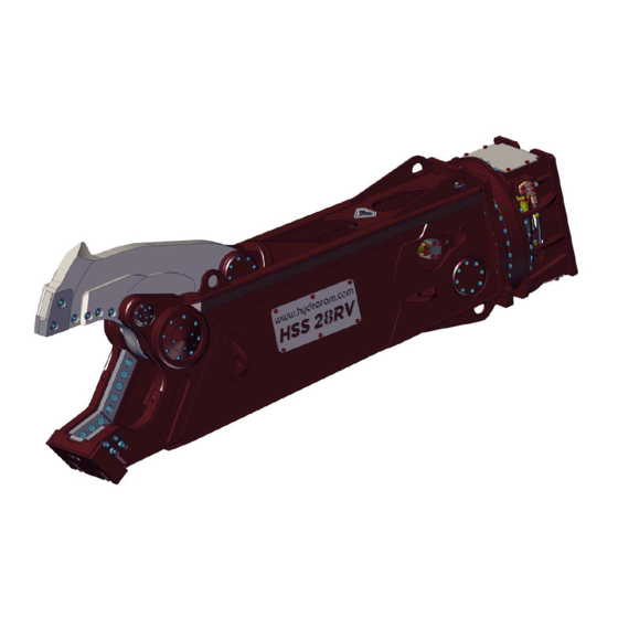
The attachment does not generate noise (sound pollution). 4. Description of the attachment 4.1. Description of the attachment The Steel Shear - HSS series is an attachment that has been fully designed and manufactured by Hydraram intended for modern industrial demolition sites which involve significant cutting effort at considerable heights and experts in recycling scrap and ferrous materials. -
Page 20: Attachment Technical Data
WARNING! The attachment is NOT suitable for use in environments that are: • Explosive. • Corrosive. • Subject to high fire risk 4.3. Attachment technical data HSS-2RV HSS-3RV HSS-6RV HSS-10RV HSS-14V HSS-22RV HSS-28RV HSS-34RV Excavatorclass 1.5 - 3 4 - 5 5 - 8 8 - 12 12 - 18... - Page 21 HSS-45RV HSS-52RV HSS-62RV HSS-82RV HSS-110RV HSS-140RV HSS-180RV HSS-220RV Excavatorclass 40 - 50 52 - 65 55 - 70 75 - 100 120 - 150 140 - 170 140 - 210 200 - 280 Weight 4380 5160 6480 8230 11680 14300 18340 21850 Jaw opening...
-
Page 22: Installation
5. Installation 5.1. Moving and handling The attachment may be shipped on wooden beams or pallets, or in a crate, depending on the destination and the customer’s request. Lifting the attachment in its packaging using cables and a gantry crane or a forklift truck. The attachment unloading, lifting and handling operations must be carried out by personnel qualified to operate lifting equipment. -
Page 23: Storage
IMPORTANT When the attachment arrives, the user must check it for any damage (breakage or significant dents) that may have occurred during shipping or unloading. If damage has occurred, immediately make it known to the transporter and add the words “ACCEPTED WITH RESERVATIONS” to the delivery document. -
Page 24: Mounting The Attachment On The Operating Machine Inbucket Position
5.4. Mounting the attachment on the operating machine inbucket position A residual risk is a hazard that cannot be completely eliminated through design and protective techniques or a potential hazard that is not obvious. The mounting procedure begins with the attachment supported stably on the ground (see figure), the operating machine engine switched off and the parking brakes engaged. -
Page 25: Mounting The Attachment On The Operating Machine In
5.5. Mounting the attachment on the operating machine in arm position WARNING! There should be a lifting device on site to carry out this kind of assembly with special coupling devices compliant with current legislation in the country in question. The mounting procedure begins with the attachment horizontally and stably positioned on the ground with adequate support, and with the operating machine engine switched off and the parking brakes engaged. -
Page 26: Use On Construction Cranes
5.6. Use on construction cranes The range of possible applications for the HSS Series hydraulic demolition attachments includes installation on construction cranes. Below is a list of operating systems, rules and requirements that must be respected when using the attachment in this way. - Page 27 TECHNICAL CONNECTION SPECIFICATIONS Hydraulic connections Attachment Operating machine Power Rotation Drainage HSS series optional optional optional 3/8” 3/8” S 16 1/4” 1/4” L 12 HSS-3RV (M24x1.5) (M18x1.5) HSS-6RV 3/4” 3/4” S 25 3/8” 3/8” S 16 HSS-10RV (M42x2) (M24x1.5) HSS-14RV HSS-22RV 1”...
-
Page 28: Stopping And Disassembly
The operating machine output pressure and flow rate must always conform to the requirements of the attachment in use (see Attachment Specifications). If this is not possible, the system must be equipped with reduction valves (contact the manufacturer of the operating machine or a specialized workshop). Do not use the attachment without check that the pressure and oil flow of the operating machine are those required. -
Page 29: Using The Attachment
WARNING! When disconnecting the hoses, take care to collect the oil in suitable containers. Do not spill oil on the ground. • In order to dismantle the attachment, follow the assembly instructions in the relative paragraph, in reverse (bucket position or arm position). •... -
Page 30: Stopping The Attachment
6.3. Stopping the attachment To stop attachment, simply leave the hydraulic distributor controls on the operating machine in the idle position. Under normal conditions, if the controls are not operated, the attachment will remain stationary. 6.4. Temporary decommissioning When the attachment is not used for prolonged periods, disconnect its hydraulic system. 6.5. -
Page 31: Regular Maintenance
• Determine maintenance intervals based on the specific requirements in relation to the production cycle of the attachment; • Every day, before using the attachment, the operator should visually inspect the general state of its components and request maintenance if they notice any strange noises or fault conditions; •... - Page 32 WARNING! Wear P.P.E. whenever carrying out scheduled maintenance. Scheduled maintenance table The machine must be isolated for maintenance. Operation Interval Every 8 hours Grease the hinges, including the slew ring, and replace any damaged grease lubricators (see Lubrication). Every 8 hours Check that none of the screws are loose or damaged.
-
Page 33: Lubrication
7.4.1 Lubrication The attachment must be lubricated at all the greasing points (G) indicated on the respective plate. Lubrication intervals must be determined based on operating conditions. The attachment must be re- lubricated before or after prolonged periods of inactivity. This is especially true for the winter break. Take care that no detergent penetrates the ball roller system or damages the gaskets. -
Page 34: Table Of Lubricants
7.4.2. Table of lubricants We have checked the compatibility of the greases shown in the table with the materials used for spacers and gaskets and consider them suitable for use in the bearings. For this reason, if the user wishes to use lubricants differing from those shown here they must obtain confirmation from the supplier or maker that the selected lubricant is suitable for use and that its specifications are at least equivalent to those of the products listed in the table. -
Page 35: Tightening The Screws
7.4.3. Tightening the screws Tightening must be performed exclusively by specialised technicians using a torque wrench and applying the torque values indicated in the table Tightening Torques and Stresses. The screws may only be re- tightened once, after which they must be replaced. Tightening Torques and Stresses 8.8-(8G) 10.9-(10K) -
Page 36: Extraordinary Maintenance
7.5 Extraordinary Maintenance Extraordinary maintenance must be carried out by a mechanic and includes maintenance, repairs and the replacement of components to ensure the attachment runs correctly. WARNING! Wear P.P.E. whenever carrying out extraordinary maintenance. Scheduled maintenance table The machine must be isolated for maintenance. Operation Interval Adjusting the clutch lock... - Page 37 Component subject to adjustment and/or wear: (A) Chassis (H) Front shim (B) Primary lower blade (L) Guide shim (C) Secondary lower blade (Q) Jaw (D) Front blade (X) Secondary upper blade (E) Guide blade (Y) Primary upper blade (F) Primary shim (Z) Tip blade (G) Secondary shim The shape of the attachment may vary depending on the model.
- Page 38 Adjustment • Partially close the jaw of the attachment so that the tip blade (Z) on the jaw (Q) meets the guide blade (E). • Slowly move the jaw (Q) and check the clearance between the tip blade (Z) and the guide blade (E) in several positions.
- Page 39 IMPORTANT! Turning the blades of the attachment increases the quality of the cut and extends the life of the blades. Tip blade The tip blade (Z) is located on the front of the jaw (Q) and is used to penetrate the material to start the cut. DANGER! When adjusting the blades, it is necessary to move the jaw.
- Page 40 Front blade The front blade (D) is located at the front of the chassis (A) and is used to improve the penetration of the jaw (Q). Adjustment • Slowly move the jaw (Q) and check the clearance between the tip blade (Z) and the front blade (D). Make sure that it never exceeds 0.4mm (it is initially adjusted to 0.15mm).
- Page 41 Replacement • If there is still excessive clearance despite using all the shims provided (H) and after having rotated it, then the front blade (D) must be replaced. • Remove the worn front blade and all the shims by loosening the screws. •...
- Page 42 Adjustment • Slowly move the jaw (Q) and check clearance between the blades on the chassis (B and C) and the blades on the jaw (X and Y). Make sure that it never exceeds 0.4 mm (it is initially adjusted to 0.1 mm). •...
-
Page 43: Clutch Adjustment And Replacement
7.5.2. Clutch adjustment and replacement The clutch lock (T1-T2) can be found on the attachment chassis (A) above the central pin and serves to guide the jaw (Q) when cutting and avoid making a dent. This is an adjustment slide which comes slightly into contact with the skimming surface (R) of the jaw. - Page 44 Replacement • Carefully close the jaw (Q) fully. • Slacken the screw (K) and remove the slide (J). • Fit the slide again. • Slacken the nut (N) and unscrew the adjustment screw (M). • Open the jaw (Q) carefully until the slide (J) is centred on the skimming surface (R).
-
Page 45: Anti-Wear Material
7.5.3. Anti-wear material Periodically, check the state of deterioration of the jaws on the attachment and replace the anti-wear material when necessary. The material must be applied in accordance with the instructions below. WARNING! • Before replacing the material, carefully remove any paint residues to avoid releasing toxic va- pours. -
Page 46: Diagnostics And Troubleshooting
7.6. Diagnostics and troubleshooting General requirements In the event of an attachment malfunction, request a specialised technician to carry out a troubleshooting investigation on it or call the manufacturer’s technical support service. Possible cause Possible solution Problem The operating machine is not ... -
Page 47: Spare Parts
Always use original replacement parts. We strongly advise against the use of non-original parts and, in the event non-original spare parts are use Hydraram may not be held responsible for the consequences of resulting breakages, malfunctions, injuries to personnel or damage to property. In addition, in such cases, the guarantee will be rendered null and void (if still valid). - Page 48 Describe the part that is not working (with the help of photographs if necessary); • Indicate the shipping method. If this field is not filled out, Hydraram while taking every care to provide the requested service, may not be held liable for any delivery delays caused by force majeure.
- Page 49 Hydraram B.V. Meander 7, 9231DB, Surhuisterveen Holland Tel : +31 512 365 981 - info@hydraram.com www.hydraram.com...
Need help?
Do you have a question about the HSS Series and is the answer not in the manual?
Questions and answers