
Summary of Contents for Opsis LD500
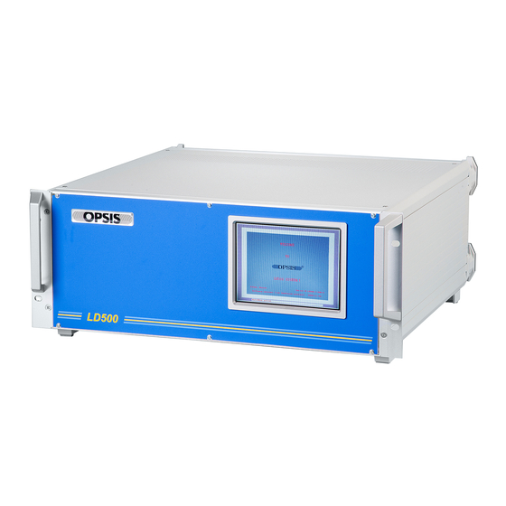
- Page 1 Opsis LD500 CEM System Emitter and Receiver Units ER060L, ER060AUTOL Installation & User´s Guide Release 1...
- Page 2 This warranty is limited to replacement of defective material or documen- tation supplied by Opsis AB and in no event shall Opsis AB or its suppliers be liable for any loss of profit or any other commercial damage, including but not limited to direct or indirect, special, inci-...
-
Page 3: Table Of Contents
The receiver RE060AUTOL ................5 1.2.3 The calibration cell ..................5 Stack port connections - port installation kit ..........6 LD500 CEM system accessories ..............7 The PM101L power supply ................7 The PW061 purge air cassette ............... 7 The optical fibres ................... 8 CU004/007 Calibration unit .............. - Page 4 7.1.2 Demultiplexers, MXn01L ................28 Switching multiplexers, SX10nL ..............28 7.2.1 Technical specification .................29 7.2.2 The DIP switches ..................29 7.2.3 RS232 port configuration ................30 7.2.4 Software configuration .................30 7.2.5 Function test of the switch ................31 7.2.5.1 The function LED´s ..................31 Maintenance ....................33 Check list for preventive maintenance ............33 Emitter and receiver ..................34 8.2.1...
-
Page 5: Emitters And Receivers
Emitters and receivers 1.1 The ER060L system The ER060L system consists of an emitter EM060L and a receiver RE060L. A power sup- ply unit PM101L is needed to power the electronics in the receiver. Figure 1.1. The ER060L system. 1.1.1 Technical specifications ER060L system EM060L/RE060L Dimensions (L ×... -
Page 6: The Emitter Em060L
Emitters and receivers 1.1.2 The emitter EM060L The EM060L can transmit light over a path length of up to 5 meters. The light is led from the laser head unit to the emitter via an optical fiber. The ending of the fiber is placed at the focal point of a parabolic mirror. -
Page 7: The Receiver Re060L
Emitters and receivers 1.1.3 The receiver RE060L The RE060L unit contains a fibre holder and a mirror. The optical components are adjust- able for the optimisation of the calibration light. Figure 1.3. The receiver RE060L. Main parts of the receiver RE060L 1 ½“... -
Page 8: The Er060Autol System
1.2 The ER060AUTOL system ER060AUTOL is designed to be used for flue gas monitoring in stacks/ducts in combina- tion with one Opsis LD500 analyzer. The ER060AUTOL consists of one emitter, EM060L and one receiver RE060AUTOL. In addition to a cross stack optical monitoring path, the ER060AUTOL provides automatic calibration function. -
Page 9: Technical Specifications
The inner diameter of the cell is 2” (53 mm) and the length is approximately 130mm. The temperature controller, TC100, is located on the control unit. The optical fiber is leading the captured light to the Opsis analyser unit, which by those means can be protected from high temperature, dust, humidity etc. -
Page 10: Stack Port Connections - Port Installation Kit
ER060AUTOL is a cross stack monitoring unit. Emitter and receiver are mounted on op- posite sides, on 1 1/2” pipe socket connections. The recommended mount is a port kit sup- plied by Opsis which includes set of 4” ANSI flanges that are attached to the stack/duct walls. -
Page 11: Ld500 Cem System Accessories
LD500 CEM system accessories 2.1 The PM101L power supply In order to operate the electronics in the receivers RE060L and RE060AUTOL, an Opsis PM101L power supply unit is required. The PM101L unit provides a ±15 V and a +6 signal to the RC101L detector card inside the receiver. -
Page 12: The Optical Fibres
2.3 The optical fibres Three qualities of laser optical fibres are available for the LD500 system. The standard fi- bre OF010 can be used in most applications. However, in applications where oxygen is measured, the fibre OF005 should be used. - Page 13 LD500 CEM system accessories Figure 2.2. Optical fibres, OF010 to the left and CF120 to the right.
- Page 14 LD500 CEM system accessories...
-
Page 15: Cu004/007 Calibration Unit 3
With a calibration cell in the measurement path (add-on calibration). A serial port in the Opsis analyser is used to control the calibration unit. The operating routines are included in the Opsis analyser software. Version number 7.10, or later, is re- quired. - Page 16 CU004/007 Calibration unit Figure 3.1. Example of an Opsis CEM system including the CU004/CU007 calibration unit for automatic calibrations. Main parts of an Opsis CEM system with automatic calibrations Emitter Power supply Receiver with built-in calibration cell CU004/007 calibration unit...
-
Page 17: Specifications
CU004/007 Calibration unit 3.1 Specifications Control unit Input voltage 120 V (± 10 %), 0.4 A 240 V (+6 %, -10 %), 0.2 A 1 × 2 A (120 V) Fuse ratings 1 × 1 A (240 V) Power requirement max. -
Page 18: Cables
CU004/007 Calibration unit 8 10 11 12 Figure 3.2. The CU004/CU007 automatic calibration unit, here shown in the CU007 ver- sion with seven valves. The CU004/CU007 consists of the following main parts, compare figure 3.2: CU004/007 main parts Cable inlets Gas inlets from gas cylinders Gas outlet to calibration cell Electrically controlled valve... - Page 19 CU004/007 Calibration unit Connected in the CU DSUB 25p female Figure 3.3. The cable between the analyser and the calibration unit. The cable is connected at position 12 in figure 3.2 as follows (connector seen as in this fig- ure): The cable between the analyser and the calibration unit left terminal black...
- Page 20 CU004/007 Calibration unit...
-
Page 21: Safety Precautions
Warning: This is a Class 3A (EC Standards) Laser Device. Caution should be taken when working with the equipment. At all work near the emitter and receiver or with the optical fibre cable connected to the LD500 analyser, safety goggles or eye protection should be used. -
Page 22: Cu004/Cu007
Safety precautions • The polished ends of the fibre are very sensitive to dust and dirt. Ensure that they are protected at all times. If they should need to be cleaned, a soft cotton cloth or lens tissues may be used, with a little alcohol if necessary. Never touch the ends of the fibres with your fingers, and do not use fabrics containing synthetic fibres for cleaning. -
Page 23: Installation
Installation 5.1 Placement conditions for the emitter/receiver Make sure that there is enough space for the emitter/receiver. The emitter/receiver must be mounted horizontally. The maximum angle is 15°. The emitter and the receiver must be mounted with a clear line of sight between them. -
Page 24: Placement Conditions For The Analyser
Installation 5.2 Placement conditions for the analyser The analyser must be placed in an air conditioned and heated instrument cabinet. One 230 V (115 V), 10 A socket must be located in the proximity of the analyser cabinet. If there are any doubts that the 230 V (115V) is not free from surges, the analyser has to be pro- tected with a surge suppressor or an Uninterruptible Power Source UPS. -
Page 25: Installation Of Er060L
ANSI flange, see figure 5.1. Figure 5.1. The support bracket. The laser output fiber from the LD500 is pulled through A, and connected on the MX102L multiplexer (A). The multiplexer splits the light signal in to two fibers of... -
Page 26: Electrical Connections
Installation which one is connected in the EM060L emitters, and the second is projected inter- nally in the RE060AUTOL unit. Make all the tubing connections according to the tubing drawing, see drawing no. 9 section 9. Connect the purge air. 5.5.1 Electrical connections Attach the flex tube to the bottom of the receiver and make all the electrical connections. -
Page 27: Light Adjustment Kit La060 6
1.5 m optical fibre. There are three ways to operate the LA060: Use it to visually align the transmitter and receiver. Use the ordinary measuring fibre to transfer light level information from the LD500 into the LA060 display. This simplifies light alignment (at the transmitter site) for long measuring paths. -
Page 28: Visually Alignment Of The Transmitter And Receiver With The La060
Connect the optical fibre included in the kit. Then connect the other end of the fibre to the optical transmitter. Put the ordinary fibre from the LD500, into the right con- nector of the LA060. -
Page 29: Measure Light Throughput To Ensure Status Of Fibre Or Light Transmitter (Version 1.2 And Up)
If there is a question of the quality of the optical throughput, use the LA060 to measure the intensity of the light. Connect one end of the fibre into the LD500 laser output, the other end into the upper right connector on the LA060. Depending on the output intensity of the laser, readings of 30-60 dB are normal. - Page 30 Light adjustment kit LA060...
-
Page 31: Multiplexers And Demultiplexers
Splitting multiplexers and demultiplexers are used when several measuring path are co- trolled by one LD500 analyser or several gases are measured. Figure 7.1. Splitting multiplexer MX10nL or demultiplexer MXn01L. Note: When ordering a splitting multiplexer or demultiplexer, the laser module type must be specified. -
Page 32: Splitting Multiplexers, Mx10Nl
Demultilexer, 4 laser modules, 1 path 7.2 Switching multiplexers, SX10nL A switching multiplexer can be used when a LD500 analyser is used for several paths and a splitting multiplexer causes an unacceptable loss of light. There are seven different types of switches, SX10nL, where n stands for the number of outputs, n = 2, 3, ..., 8. -
Page 33: Technical Specification
Rx 1 3 5 7 PWR Figure 7.5. The front side of the switch . On the back side of the switch there are fibre connectors, the input from the LD500 analys- er and 2-8 connectors for the outgoing fibres, depending on model. -
Page 34: Rs232 Port Configuration
7.2.3 RS232 port configuration The switch is connected to the LD500 analyser via a straight RS232 cable with a male con- nector in one end (SX side) and female in the other (LD500 side). Master port, 9 pin Dsub female, DTE... -
Page 35: Function Test Of The Switch
Multiplexers and demultiplexers changed. Move the cursor to the column Config and press [Enter]. The menu Com port setup opens, where it is possible to configure the port that the switch is connected to. It is possible to use the SX10nL together with splitting multiplexers. In the multiplexer set- up menu this option can be set. - Page 36 Multiplexers and demultiplexers...
-
Page 37: Maintenance
Maintenance Maintenance of the Opsis LD500 system should be scheduled and followed on a regular basis to ensure proper operations and prevent the possibility of malfunctions. Maintenance records should be kept in a log book at the monitoring location. 8.1 Check list for preventive... -
Page 38: Emitter And Receiver
Maintenance 8.2 Emitter and receiver 8.2.1 Cleaning the mirrors and windows The protective windows are made of quartz, and cleaning causes no problems. Dirt and grease can be removed using a soft cotton cloth with acetone or pure alcohol. The mirrors are made of a thin layer of aluminium which is sputtered onto a quartz sub- strate. -
Page 39: Installation Drawings
Installation drawings Drawing no. Description Connecting flange Welding flange Connecting flange Emitter EM060L Receiver RE060L Receiver RE060AUTOL ER060AUTOL system, electrical drawing ER060AUTOL system, optical fibres ER060AUTOL system, tubing... - Page 40 Installation drawings...
- Page 41 Drawing no. 1. Connecting flange...
- Page 42 Drawing no. 2. Welding flange...
- Page 43 Drawing no. 3. Connecting flange...
- Page 44 Drawing no. 4. Emitter EM060L...
- Page 45 Drawing no. 5. Receiver RE060L...
- Page 46 Drawing no. 6. Receiver RE060AUTOL...
- Page 47 Drawing no. 7. ER060AUTOL system, electrical drawing...
- Page 48 Drawing no. 8. ER060AUTOL system, optical fibres...
- Page 49 Drawing no. 9. ER060AUTOL system, tubing...
-
Page 51: Appendix: Er060Autol Setup
Appendix: ER060AUTOL setup The configuration is made in the following steps. Enter the IO256 software, section A.1 Set up units (protocol: IOMan) for communication between the analyser and the IOMan modules, section A.2. Load and save the settings from the IOMan modules (inputs and outputs), section A.3. -
Page 52: Load The Settings From The Ioman Modules
Enter the IO256 software. Choose Input => Channel setup. For the channel con- nected select Type = “Pt100”, Input range = “direct”, Scaled range = “direct” and Name = “celltemp”. Repeat step 1 for the other input signals. LD500 IO256 input Protocol Channel type... - Page 53 Appendix: ER060AUTOL setup Press [F1] Cylinder/CU007 settings. Press [F2] to switch between digital and serial. Choose serial. Press [F3] Com port setup. In the menu the following information is entered: • Com port • • The baud rate is set to 9600. The rest of the settings are default.
- Page 54 Appendix: ER060AUTOL setup...
Need help?
Do you have a question about the LD500 and is the answer not in the manual?
Questions and answers