Table of Contents
Advertisement
Quick Links
Advertisement
Table of Contents

Summary of Contents for CNCdrive DG4S Series
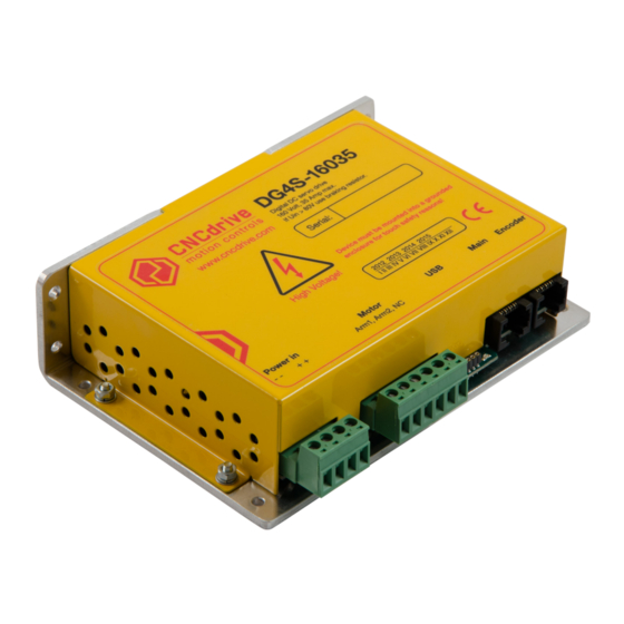
- Page 1 DG4S series DC Servo drive...
- Page 2 DG4S series DC Servo drive User’s Manual and Installation Guide CONTENTS warranty Safety, policy and Installation of drive and physical dimensions / 12 – 16 Safety Notes Policy Motor wiring Warranty Encoder wiring Shielding techniques in general Electric specifications and limitations / 4...
-
Page 3: Safety Notes
1.3 Warranty We give 12 months of standard warranty period with our DG4S series drives. Customers may send back the drives within 15 days from reception date if they are not satisfied with the performance. -
Page 4: Operation Ranges
Electric specifications and limitations 2.1 Operation ranges Property Unit Notes Motor supply voltage Optimal U=rated+10..20% (model 08020) Motor supply voltage Optimal U=rated+10..20% (model 16035 without using braking circuit) 1.) Optimal U=rated+10..20% Motor supply voltage 2.) >160VDC input Votlage (model 16035 with using may cause permanent dam- braking circuit) age to the device! - Page 5 Property Unit Notes Opto-isolator current Step input frequency Direction signal stabile state Step signal active and inac- minimum allowed valid time usec tive edges can be config- after step signal active edge ured in software by user. Encoder maximum frequency With 4x decoding 100mA continiously output Error line output current...
- Page 6 Connectors Power in Motor Main Encoder 3.1 Power in and motor connectors Description of the Motor connector: Connect the DC servomotor terminal wires to Motor Arm1 and Motor Arm2 screw terminals. There are 2 connection terminals for motor Arm1 and also 2 connections for Arm2. For low power motors (peak current rating<20A) enough to connect 1-1 terminals.
- Page 7 3.2 USB, Main and Encoder connectors Description of the USB interface connector: A 4-pin RM2.0 socket connector is provided for tuning and for making diagnostics on the drive. This connector plugs directly into our PRG01 USB programming stick and this cable con- tains the USB driver electronics.
- Page 8 Description of the Main connector: The socket labeled Main is a standard RJ45 socket and contains control and fault signal pins. The pinout of the Main connector is listed below: Step signal input Direction signal input Ground for Step and Direction signals (NOT for power) 5V power input.
- Page 9 Error (and Stop) See Chapter 4.2 for features and function of the Error line. See Chapter 5.4 for Error line connection options. Note: A Stop signal can be sent on the Reset line or on the Error line. Ground- ing either of these pins will stop the drive, but in different ways. See Chapter 4.2 for Error line function.
-
Page 10: Led Indicators
See Chapter 5.4 for details on Error line connection options. Fault handling by the DG4S series drives: The possible operation states and their indications are as follows: 1. Controller running - indicates normal operation of the controller. - Page 11 2. Limit override - indicates that the set servo error limit is reached. Red LED blinking and Green LED blinking simultaneously. Description: This is a fault condition and occurs if the following servo error gets greater than the user set value. 3.
- Page 12 Installation of drive and physical dimensions 3,500 90° Figure 4. Drive mounting dimensions All dimensions in mm. The drive has four-four 3.5 mm mounting holes in the 3 mm thick aluminium backplate. The backplate is bent to 90° and is mountable in the vertical and also in the horizontal orientation.
-
Page 13: Motor Wiring
Use heat transfer paste or a silicon heat transfer sheet to get the best thermal connection between the drive’s metal backplate and external mounting metal frame. The drive has builtin thermal protection, but it is adviced to keep the metal frame as cool as possible to avoid overheating and unexpected shutdowns. - Page 14 To protect your new drives and also for the most reliable communications between the computer and the CNC electronics, always use separated Power Supplies for the digital power and the motor power and do not connect the two GND points together, keep them separated and run the ground lines back to their respective power supplies.
- Page 15 5V from AUX port pin 1. Drive 1. Optoisola 470 R ~100k PC input Error line PC GND Internal External External control control pushbutton logic logic GND from AUX port pin 2. Drive 2. ~100k Error line Internal control logic Drive n.
- Page 16 5.6 Mixing the Reset and Error lines The error line acts as an opencollector output which means that many error lines can be connected together (paralelled or in other words OR wired). The reset line is an input and therefor any number of reset lines may be also wired to- gether.
- Page 17 Power Supply selection and filtering The drive needs 2 power supplies for operation, one to feed the digital circuit and one to feed the motor. The digital power supply can be tipically a 12V DC voltage source with that has smoothed and regulated output and meets the other electrical requirements. The motor power supply should be a ‘linear’...
- Page 18 Using a switching mode power supply (SMPS) If using not a linear, but switching mode power supplies then do not connect the SMPS outputs directly to the drives, but connect a diode with it’s anode to the power supply positive output and place a capacitor to between the diode’s cathode and the negative (GND) output of the SMPS.
- Page 19 Accessories (not parts of the drive, may be ordered separately!) DRVE Differential line driver module Pinout: 1. Ground 2. 5V DC power for encoder 3. Not used 4. Not used 5. A 6. A_ 7. B 8. B_ Ground 5 Volt Figure 8.
-
Page 20: Troubleshooting
Troubleshooting Q: When powering up the drive, the motor running with full speed to one direction and stops after a while with error-limit reached LED on. A: Encoder is wired up in reverse, exchange motor Arm1 with Arm2 to reverse direction of the motor. - Page 21 CONTENTS...
- Page 22 For more information visit: www.cncdrive.com Please consider the enviroment before printing this document. CONTENTS...
Need help?
Do you have a question about the DG4S Series and is the answer not in the manual?
Questions and answers