Table of Contents
Advertisement
Quick Links
Advertisement
Table of Contents

Summary of Contents for Veneroni AT
- Page 1 PUMPS TYPE AT - ET Manual cod. 995-0005 - Ed. 10/2021 rev.10...
- Page 2 We congratulate you for having chosen our machine. We are sure that following the instructions contained in this manual, you will come to highly value our product. For a correct use of the machine it is compulsory, both for the operator and for all the people who will have to operate on it, to read it attentively and to conserve it carefully;...
-
Page 3: Table Of Contents
9 Machine’s uses ................. Technical description of functions ..........Work place ................Controls and operation ............10 Machine accessories and components ..........10.1 AT machine accessories ............10.2 Position of delivery curve ............10.3 Delivery curve with shock absorber .......... 10.4 Command for the activation of the hydraulic motor for automatic calibration of the delivery tube .......... - Page 4 14 Instructions for disassembly and storage ..........14.1 Disassembly instructions ............14.2 Storage instructions ............... 15 Maintenance instructions ..............16 Training personnel ................17 Disassembly of the machine ............. 18 Warranty ..................Declaration of compliance ..............19 Tables....................
-
Page 5: Symbols
SYMBOLS The following warnings are used in this manual. WARNING: Important safety message! READ consult the manual carefully before using the machine WARNING: use safety gloves Wear safety glasses or visor, gloves and safety clothes Follow very carefully all indications for repair shown in this manual! -
Page 6: Summery Of Machine Parts
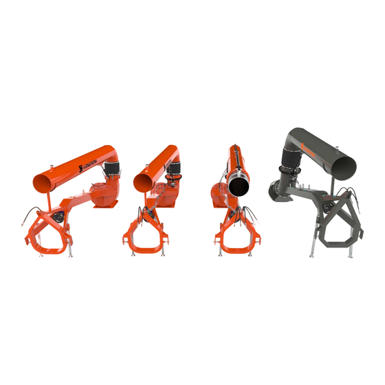
SUMMERY OF MACHINE PARTS 1. Type AT: mobile pump with tubular frame that attaches to the hydraulic lifting apparatus of the tractor. Es.: AT30/4 = mobile pump type AT = tube exit diameter in cm = Nominal frame length in meters 2. -
Page 7: How To Use And Keep The Manual
In the event that the manual is damaged or lost, a new copy can be requested from the Ma- nufacturer or the Distributor. The Manufacturer advises that the manual refl ects the state of machine at the time when the machine was distributed and cannot be considered inadequate only because it may have to be updated in line with new knowledge acquired. - Page 8 If the Client would like to receive additional information or make suggestions for the manual, they can directly contact the manufacturer or the reseller. If the machine is sold, the client is requested to inform the constructor or reseller of the new owners address so that any new manuals can be sent to them.
-
Page 9: Machine Description
MACHINE DESCRIPTION AT-ET pump type for mobile installations. The Pumping machine type AT-ET is made up essentially of the following components, see fi gure 5.1: Attachment “third point” Parallel attachments Supporting feet Blockage pin supporting foot Supporting plate Tubular frame... - Page 10 Fig.5.1...
-
Page 11: Technical Data
5.1 Technical Data Technical characteristics and performance. AT type pump performance Power Max load* Min/turns absorbed* Model P .T .O. mc/h Power take-off 3350 1800 2810 4350 2700 3810 AT 25/ 5350 3600 4810 6350 4500 5810 3400 1800 2825... - Page 12 ET/50 type pump performance Power Max load* Min/turns absorbed* Model P .T .O. mc/h Power take-off 5340 3300 3450 ET 50/ 2880 6340 4000 4450 * With 4 m head Note: The machine’s noise emissions are less than those of the tractor it is connected to. Therefore for noise emission information consult the manual for the relative tractor.
-
Page 13: Lubrication
6 LUBRICATION Fig.6.1 Lubricate all points indicated with the symbol (see fi g 6.1), with the pump switched off. For when and how to lubricate consult chapter 15 MAINTENANCE INSTRUCTIONS on page 36. WARNING: ! During the lubrication ense that the transmission is switched off. To carry out a proper lubrication of the rotation, use the lubricators placed on the flange of the articulation. -
Page 14: Security Warnings
SECURITY WARNINGS Fig.7.1 Keep hand away from this area: Danger of being crushed Keep at a safe distance: Cardan joint in use Attachment points for lifting Keep at a safe distance: Moving parts Read the operating manual before starting this machine... -
Page 15: Accident Prevention Regulations
ACCIDENT PREVENTION REGULATIONS Incorrect usage. The machine must NOT be used if safety devices are NOT installed, NOT con- nected; NOT calibrated, voluntarily removed or ineffi cient as this can lead to being caught, dragging or breakage. The machine must not be activated for pumping liquid where there are solid external mate- rials (gravel, wood, etc.), this may cause the blockage and breakage of the machine. - Page 16 WARNING Sharp corners and edges. Exercise caution when in contact with the machine because on impact these parts can cause bruising or injury but otherwise the machines surface is not dangerous to handle. WARNING Mobile elements. Do not lean on the cardan shaft during the machine’s operations: there is a danger of being dragged (see the user manual and maintenance booklet of the cardan).
- Page 17 Fig.8.1 WARNING When the pump is activated ensure that no persons are near the: tube there is a risk of being crushed WARNING When the pump is switched off the delivery tube is lifted into the rest position: ensure that there are no persons in the effected area: there is a danger of being crushed.
-
Page 18: Machine's Uses
MACHINE’S USES Areas of operation: direct irrigation, lifting and transporting water. Water used: clean or dirty (containing mud) water Function : attach to tractor using a cardan shaft Usage: the pump is connected to the hydraulic lifter of the tractor. Technical description of functions. -
Page 19: Controls And Operation
Fig.9.2 The machine AT-ET has the following commands (Fig. 9.2): 1. Blockage and release turning fl ange leavers for manual curve calibration (A) only (AT) (AT50 and ET50 rotate hydraulically); 2. Screws for the calibration of the shock absorber (B) (only AT without hydraulic jack);... -
Page 20: Machine Accessories And Components
MACHINE ACCESSORIES AND COMPONENTS. Fig.10.1 10.1 AT machine accessories. A. Flow protection B. Shock absorber (usually the hydraulic jack but if requested the shock absorber is available for all pumps, apart from the AT35, AT40 and the 6m AT50). C. 3° hydraulic point D. -
Page 21: Position Of Delivery Curve
Fig.10.2 10.2 Position of delivery curve (fi g. 10.2) The rotation is obtained manually pushing the tube (1) after releasing the lever (2) of the turning fl ange (3). 10.3 Delivery curve with shock absorber When the tube (1) is fi lled with water, it automatically lowers until it leans on the ground. The shock absorber (4) stops the tubes movement and puts it into the rest position using a spring. -
Page 22: Command For The Activation Of The Hydraulic Motor For Automatic Calibration Of The Delivery Tube
10.4 Command for the activation of the hydraulic motor for automatic calibration of the delivery tube and the jack (pump type AT-ET with hydraulic rotation). The commands are on the tractor therefore consult its user manual for operation. The hydraulic motor can rotate the delivery curve in both directions : 180° in the version with the hydraulic jack and without limitations in the version with the shock absorbers (fi... -
Page 23: Shifting The Machine
Lifting the machine must be done on a carrier vehicle with an appropriate chord that meets requirements of safety laws that can sustain a maximum load of: AT Pump Kg 1200 ET Pump Kg 1500 The point where the chord must be attached for lifting is indicated in fi... - Page 24 Fig.11.2 Ensure that the tractor unit that the pump is hooked up to, is provided with the appropriate mass and power capacity suitable enough to support the pump in question:for verify see the table at pag.40 of this manual. Fig.11.3...
- Page 25 Lift the machine with the hydraulic lifter of the tractor so that the position is similar to fi gure 11.4. Remove the pins as indicated in fi gure 11.5 and lift the supporting feet. reinserting the pins. Fig.11.4 Fig.11.5 During transport, make sure always that the delivery pipe is resting firmly on the storage facility (pos."A"...
-
Page 26: Positioning And Operation
POSITIONING AND OPERATION 12.1 Operation, materials and equipment for usage The machine, as supplied, does not need any specifi c materials or equipment to be used. A single person can attach or detach the machine from the parallel bar and the third point of the tractor. - Page 27 4. If the pump is supplied with a hydraulic distributor with remote control, put the commands in the tractor; Fig.12.3 WARNING! Danger of collision, damage or breakage: movement operate care- fully and at a moderate speed. Remember that the longer the pump, the more dangerous it is to shift.
- Page 28 5. When arrived on location position the delivery tube in the desired location, as described in paragraph 10.3, before positioning the pump into the irrigation canal. For pumps equipped with hydraulic rotation of the delivery tube, the calibration can be done from the machine in position Fig.12.4 6.
- Page 29 Fig. 12.6 WARNING! Danger of damage or breakage During the machine's operation check that the delivery tube always rests on the ground, as shown in fig.12.6. WARNING Danger of damage or breakage: height difference of power takeoff. Align the two power takeoffs, motor and pump, so that the working angle of the cardan shaft is equally distributed between both spiders.
-
Page 30: Instructions For The Use, Calibration And Starting Of The Machine
WARNING! If the machine is used at night or in a low light area, it is essential to illuminate the working area so that the operator can perform all duties easily. 13.2 Instructions for finishing work... -
Page 31: Maintenance Of Hydraulic System
Identify the damaged tube and loosen using the appropriate 2 point key be careful as lubrica- ting fl uid might leak. Substitute the hydraulic tubes fi ve years at the latest after the date of purchase. Ensure that all the attachment points (threads, washers etc) are in perfect condition before installation of the new tube. -
Page 32: Instructions For Disassembly And Storage
INSTRUCTIONS FOR DISASSEMBLY AND STORAGE 14.1 Disassembly instructions The person who is responsible for disassembling the machine (or the operator) is obliged to read and follow the instructions presented in this manual. Referring to the fi gures, the operations necessary to disassemble the machine safely are de- scribed below: 1. - Page 33 Fig.14.2 4. Put the tubes in the transport position using levers (A) fi gure 14.2; 5. Pumps with hydraulic delivery tube rotation should be moved using the command levers of the hydraulic motor to bring the tubes to the transport position;...
-
Page 34: Storage Instructions
It is recom- mended also to grease the transmission parts at the end of the season (for lubrication points see fi gure 6.1 on page 14). -
Page 35: Maintenance Instructions
MAINTENANCE INSTRUCTIONS WARNING: use safety gloves The person who is responsible for disassembling the machine (or the operator) is obliged to read and follow the instructions presented in this manual. When maintenance is performed on the machine, it must be still and disconnected from the tractor (removal of cardan shaft). The maintenance points are as follows : 1. -
Page 36: Training Personnel
4. Dynamic oil tubes : Periodically check the functionality of the tubes and substitute if necessary (pump type ET or AT rotation of delivery tube and hydraulic jack is hydraulically operated) TRAINING PERSONNEL The machine is simple to use and does not require specifi c training to use, but the operator must have completely read this manual. -
Page 37: Warranty
The warranty does not include any costs relative to the disassembly, reassembly, transport, transferral board and accommodation of technical if required by the client. The warranty services will take place exclusively in the main VENERONI srl offi ce or that of authorized resellers. -
Page 38: Declaration Of Compliance
UNI EN ISO 12100-2010 CEI EN 60204-1 CEI EN 61439-1 VENERONI SRL undertakes to transfer in response to a request properly supplied by the national authorities, information on the machine VENERONI SRL AUTHORIZE Mr. Pietro Veneroni Via della Resistenza, 8 - 26020 FORMIGARA (CR) – ITALIA... -
Page 39: Tables
19 TABLES Here following the formula for the control of the tractor’s stability with coupled machine during circulation: In which: i tractor axial wheel base d distance between center of the front axl and barycenter of the ballasts S1 distance between center of the rear axl and center of the attachment inferior points S2 distance between center of the inferior attachment points and barycenter of the machine T weight of the tractor plus 75 kg (operator medium weight) Z ballasts weight (if not available, consider the value Z=0) P machine weight IF THE CONDITION PROVIDED BY THE ABOVE SPECIFIED FORMULA IS NOT OBSERVED, CIRCULATION IS FORBIDDEN. ... - Page 40 The values S2 e P are provided by the manufacturer of the machine and indicated in the following table ( values L, W and H do not refer to the formula, they are provided because characteristics of the machine) The values referred to the tractor are not provided by the manufacturer of the machine. ...
- Page 41 VENERONI PRODUCE LE SUE MACCHINE VENERONI PRODUCES ITS MACHINES UTILIZZANDO ENERGIA PULITA. USING CLEAN ENERGY. SOSTENIAMO LE ENERGIE RINNOVABILI. WE SUPPORT RENEWABLE ENERGIES. https://prom-nasos.pro https://bts.net.ua https://prom-nasos.com.ua +38 095 656-37-57, +38 067 360-71-01, +38 063 362-12-31, info@prom-nasos.pro...
Need help?
Do you have a question about the AT and is the answer not in the manual?
Questions and answers