
Summary of Contents for Robodyssey Mini Roach
- Page 1 Robodyssey Mini Roach Assembly Instructions Version 1.1 Robodyssey Systems, LLC. Phone/Fax: 609-585-8535 20 Quimby Avenue Web: www.robodyssey.com Trenton, New Jersey 08610 Email: info@robodyssey.com Copright 2002 Robodyssey Systems, LLC. All Rights Reserved...
- Page 2 2. Mini Roach Kit Contents Roach Body Center Servo Support Primary Legs (4) Small Screw Bag Center Legs (2) Linkage Bag Servos (3) Pivots and Spacer Bag Roach Head Long Linkages...
- Page 3 Part 7 Small Screw Bag 6-32 inch screws (4) 4-40 inch button heads (4) 4-40 ¼ inch button heads (2) 6-32 ¼ inch button heads (8) Part 8 Linkage Bag Nylon Ball Sockets Steel Ball Ends 2-56 Nuts Mid (3) and short (1) Threaded Rod Pivots and Spacer Bag Part 9 Female Binder Post (6)
- Page 4 Assembly Instructions Assembly of the Mini Roach kit will take you about 60 minutes. Be sure to look up the proper part for each step, indicated by the number next to the part name which corresponds to the pictures in “Mini Roach Kit Contents.”...
- Page 5 Now attach six Ball Pins (12) using the Small Nuts (13) to the holes in the Primary Legs (2). Note that one pair of legs has two ball pins each, while the other pair only has one ball pin per leg in the innermost hole. Assemble as shown in Figure 4.
- Page 6 Secure the leg in place with the threaded portion of the Binding Post (16). As shown in Figures 9 and 10. Care should be taken as to not over tighten the screw. The leg should be able to turn with little resistance. Figure 9 Figure 10 Repeat the above steps until all 4 Side Legs (2) are installed.
- Page 7 Place a 1/8 inch Nylon Washer (17) over the Binding Post (15). See Figure 13. Figure 13 Start by attaching the leg that has only one ball pin. Orient the leg such that the ball pin points toward the back of the Roach body. The back of the Roach body is the end with the rectangular openings cutout for servos.
- Page 8 Servo mounting instruction Note: It is not recommended to rotate any servo by turning the horn! Robodyssey recommends centering servos electronically. See appendix A for a simple software routine to center servos connected to a Robodyssey advanced motherboard equipped with a Basic X processor. Always exercise caution when running a servo the first...
- Page 9 Insert a centered Servo (4) into one of the rectangle cut outs in the rear of the Roach. Secure it in place with four 6-32 button head screws (21). See Figure 20 Figure 20 Repeat with the other side. You should now have a robot that looks like the one in Figure 21.
-
Page 10: Connecting The Linkages
Place a servo horn with a ball securely attached to the center hole on the servo spline. With the servo in center, place the horn over the shaft such that the horn points in the direction of the arrow. Be sure to secure the horn in place with a small servo screw. - Page 11 Place the Roach on a flat surface and position the legs perpendicular to the body and parallel to each other. Snap one end of the long threaded rod on one of the inner balls. Adjust the length of the bar by tightening or loosening the ball socket ends until the bar is the right length to secure the legs together while maintaining their position.
- Page 12 Figure 30 Figure 31 Attach two Ball End Sockets (11) to either side of a Mid length threaded rod (14) as shown in Figure 31. Figure 31 Attach the linkage first to one side then to the other as shown in Figures 32 and 33. As before, adjust the length of the rod so that as the servo arm stays in its mid point, the leg stays in its mid point as well.
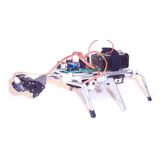
- Page 13 Attach the Head (5) with two 4-40 ¼ inch screws (20) as shown in Figure 36. Figure 36 Attaching a Robodyssey Advanced Motherboard (RAMB). (If optionally equipped) Place three ¼ inch nylon spacers on the back of the Roach. Note: Only two will line up with holes in the front.
- Page 14 Figure 39 Place the Velcro strap through the body as shown in Figure 40. Figure 40 Figures 41 and 42 show the mounting of the Robodyssey adjustable Sharp bracket. Figure 41 Figure 42...
- Page 15 Plug in a battery and YEA! Your Done! Appendix A Servo centering code PulseOut sends a signal out the pin X for whatever time (in this case 0.0015 sec) ‘***************************************************************** Option Explicit Public Sub Main() Dim j as Integer ‘ Number of pulses the servos receives For j = 1 to 20 ‘...
- Page 16 '************************ROACH************************** 'Mini Roach - Hexapod w/ Forward Sharp Sensor '@ Version 1.0 '@ Author: Brian Patton '@ Last Updated: Oct 15, 2003 '******************************************************** '************* Declare Constants ************************ Public Const LeftServo As Byte = 6 ‘ Left servo connected to RAMB pin 1 Public Const RightServo As Byte = 5 ‘...
- Page 17 SensorValue = GetADC(IRPin)+GetADC(IRPin)+GetADC(IRPin) ' Get three IR readings SensorAve = Sensorvalue \ 3 ' Divide them by 3 to get the average ' Helps eliminate some error Debug.Print CStr(SensorAve) ‘ Print value on the screen If Sensorave > 500 Then ' See if something is too close Call TurnRight ' Call right...
- Page 18 CenterServoPos = CenterServoLeft RightServoPos = RightServoMid Call SendServoCommands() CenterServoPos = CenterServoRight LeftServoPos = LeftServoMid Call SendServoCommands() CenterServoPos = CenterServoMid Call SendServoCommands() Sleep(2) End Sub '******************************************************** '******** Send Commands to Servos *********************** Sub SendServoCommands() Dim j As Byte For j = 1 to ServoPulses Call PulseOut(CenterServo, CenterServoPos, 1) Sleep(ServoCommandSleep) Next...
Need help?
Do you have a question about the Mini Roach and is the answer not in the manual?
Questions and answers