Table of Contents

Summary of Contents for CEASE FIRE CFX-Plus Pro-Sense 8
- Page 1 CEASE FIRE PR®-SENSE THE CONVENTIONAL FIRE ALARM SYSTEM INSTALLATION, COMMISSIONING & OPERATING M ANUAL FOR EN54 APPROVED 8 - 12 ZONE CONVENTIONAL CONTROL PANEL APPROVED BY 810a/10 Approved Document Ref: UI-CFX-Plus-PS-02 Issue 1.0...
- Page 2 Uttarakhand, India, Pin 248001 CPR Number Model Number LPCB Ref No. 2831 CPR F2803 CFX-Plus Pro-Sense 8 zone conventional panel: TI-002308 810a/10 CFX-Plus Pro-Sense 12 zone conventional panel: TI-002309 810a/11 2831 CPR F2803 European Standard EN54-2 : 1997 + A1 : 2006 Control and indicating equipment for fire detection and fire alarm systems for buildings.
-
Page 3: Table Of Contents
SERVICE & MAINTENANCE DUTIES OF THE RESPONSIBLE PERSON ROUTINE MAINTENANCE & TESTING SCHEDULE OF TESTING LOG BOOK FALSE ALARMS, FAULTS & ENGINEER VISIT LOG BOOK USER INSTRUCTIONS CFX-Plus Pro-Sense 8-12 Installation, Commissioning & Operating Manual Approved Document Ref: UI-CFX-Plus-PS-02 Issue 1.0... -
Page 4: About This Panel
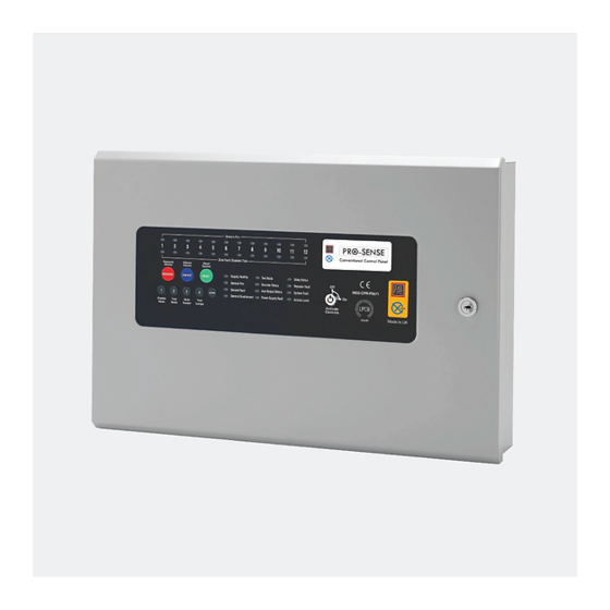
ABOUT THIS PANEL PRODUCT OVERVIEW The CFX-Plus Pro-Sense 8 to 12 zone is a conventional control panel with integral power supply & space for standby batteries. CFX-Plus Pro-Sense panels are fully approved to European standards EN54-2 & 4, Fire Detection and Alarm Systems - Control &... -
Page 5: Cabinet Details
ABOUT THIS PANEL CABINET Fire Detection System CFX-Plus Pro-Sense 8-12 Installation, Commissioning & Operating Manual Approved Document Ref: UI-CFX-Plus-PS-02 Issue 1.0... -
Page 6: Circuit Boards
ABOUT THIS PANEL CIRCUIT BOARDS CFX-Plus Pro-Sense 8-12 panels comprise of two main circuit boards plus optional ancillary boards TPCA01-X2/X4 - Master PCB 28V 0V FIRE FAULT SNDR1 SNDR2 ZONE1 ZONE2 ZONE3 ZONE4 C NC NO C NC NO -OP -OP... - Page 7 1 1 1 1 1 2 3 4 ADDRESS • Piggy backs on Main PCB for connection to network & repeater panels • 6 programmable switch -ve outputs CFX-Plus Pro-Sense 8-12 Installation, Commissioning & Operating Manual Approved Document Ref: UI-CFX-Plus-PS-02 Issue 1.0...
-
Page 9: Zone Card Terminals
ZONE A ZONE B ZONE C ZONE D + - + - + - + - TWIN C NO OPA OPB SNDR A SNDR B CFX-Plus Pro-Sense 8-12 Installation, Commissioning & Operating Manual Approved Document Ref: UI-CFX-Plus-PS-02 Issue 1.0... -
Page 10: Technical Specification
Supply output Fused @ 500mA Programmable outputs 1 - 6 Switched -ve outputs Overload voltage protected to 52V DC Current limited 680R Max load = 40mA CFX-Plus Pro-Sense 8-12 Installation, Commissioning & Operating Manual Approved Document Ref: UI-CFX-Plus-PS-02 Issue 1.0... -
Page 11: Power Supply Module
Resistance = 1 Ohm or greater 1 Hour reporting time Max current drawn from batteries 3.15 Amps with main power source disconnected. Battery fuse 3.15A LBC 20mm. CFX-Plus Pro-Sense 8-12 Installation, Commissioning & Operating Manual Approved Document Ref: UI-CFX-Plus-PS-02 Issue 1.0... -
Page 12: Design Considerations
For areas where people are sleeping, sounder devices should produce a minimum 75dB(A) at the bed-head with all doors shut. In buildings providing sleeping accommodation for a significant number of people, all bedrooms should have both audible and visual alarms. CFX-Plus Pro-Sense 8-12 Installation, Commissioning & Operating Manual Approved Document Ref: UI-CFX-Plus-PS-02 Issue 1.0... - Page 13 All system wiring should be installed to meet BS5839 Pt 1 : 2002 and BS7671 (Wiring Regulations). Other national standards of installation should be used where applicable. CFX-Plus Pro-Sense 8-12 Installation, Commissioning & Operating Manual Approved Document Ref: UI-CFX-Plus-PS-02 Issue 1.0...
-
Page 14: General Detection Circuit Schematic
GENERAL DETECTION CIRCUIT SCHEMATIC 4K7 OHM END OF LINE RESISTOR TI-002270 BASE 45681-201 MANUAL CALL POINT TI-002269 1 2 3 4 TI-002270 BASE 45681-201 TI-002270 BASE 45681-201 ZONE 1 CFX-Plus Pro-Sense 8-12 Installation, Commissioning & Operating Manual Approved Document Ref: UI-CFX-Plus-PS-02 Issue 1.0... -
Page 15: General Sounder Circuit Schematic
DESIGN CONSIDERATIONS GENERAL SOUNDER CIRCUIT SCHEMATIC 4K7 OHM END OF LINE RESISTOR MOTORISED BELL POLARISED MOTORISED BELL POLARISED ELECTRONIC SOUNDER POLARISED ELECTRONIC SOUNDER POLARISED SNDR1 CFX-Plus Pro-Sense 8-12 Installation, Commissioning & Operating Manual Approved Document Ref: UI-CFX-Plus-PS-02 Issue 1.0... -
Page 16: Installation
This product has been manufactured in conformance with the requirements of all applicable EU Council Directives CFX-Plus Pro-Sense 8-12 Installation, Commissioning & Operating Manual Approved Document Ref: UI-CFX-Plus-PS-02 Issue 1.0... -
Page 17: Esd Precautions
Knockouts should be removed with a sharp tap at the rim of the knockout using a flat 6mm broad bladed screwdriver. Use of excessive force will damage the enclosure around the knockout. CFX-Plus Pro-Sense 8-12 Installation, Commissioning & Operating Manual Approved Document Ref: UI-CFX-Plus-PS-02 Issue 1.0... -
Page 18: Mains Connections
Sufficient earth lead should be left to allow Live and Neutral connections to be accidentally pulled from the terminal block while leaving the earth connection intact. CFX-Plus Pro-Sense 8-12 Installation, Commissioning & Operating Manual Approved Document Ref: UI-CFX-Plus-PS-02 Issue 1.0... -
Page 19: Connecting The Batteries
When the panel is re-charging a low battery, it should be possible to see the voltage across the batteries increase gradually. If this is not occurring, the batteries or the panel may be faulty. CFX-Plus Pro-Sense 8-12 Installation, Commissioning & Operating Manual Approved Document Ref: UI-CFX-Plus-PS-02 Issue 1.0... -
Page 20: Setup & Programming
8-12 this is switch 7 on the 7 way DIL switch. OFF = Stand Alone mode, ON = Network/Repeater mode. With this switch in the ON position the panel will automatically recognise & operate the Comms PCB (TPCA05). !"# &# CFX-Plus Pro-Sense 8-12 Installation, Commissioning & Operating Manual Approved Document Ref: UI-CFX-Plus-PS-02 Issue 1.0... - Page 21 See panel wide programming settings, code 2-1-2-3, option 6, (Change Network/Repeater Comms Monitoring Type). CFX-Plus Pro-Sense 8-12 Installation, Commissioning & Operating Manual Approved Document Ref: UI-CFX-Plus-PS-02 Issue 1.0...
-
Page 22: Zone Interface Function
Example connection Z Z ONE2 ZONE2 ONE2 C NC NO C C C + - + - FAULT FIRE CFX-Plus Pro-Sense 8-12 Installation, Commissioning & Operating Manual Approved Document Ref: UI-CFX-Plus-PS-02 Issue 1.0... -
Page 23: Level 3 Engineering Mode
Pressing ENTER again will exit ‘edit’ mode back to ‘review’ mode. Some programming modes are denoted with (EN54!). Where this symbol appears EN54 compliance may be affected by this setting. CFX-Plus Pro-Sense 8-12 Installation, Commissioning & Operating Manual Approved Document Ref: UI-CFX-Plus-PS-02 Issue 1.0... - Page 24 Alarms’, ‘Evacuate’, ‘Class Change’, ‘Alert’ and ‘Delay’ System Diagnostics Mode Tests system PCB config setup for fault diagnosis 3114 Repeater Programming Repeater panel setup & programming 4443 CFX-Plus Pro-Sense 8-12 Installation, Commissioning & Operating Manual Approved Document Ref: UI-CFX-Plus-PS-02 Issue 1.0...
- Page 25 Amber, fault LEDs 1 - 8 indicate which repeater had a PSU fault When finished, enter the next programming code or disable the controls and return DIL switch 6 to ‘OFF’. CFX-Plus Pro-Sense 8-12 Installation, Commissioning & Operating Manual Approved Document Ref: UI-CFX-Plus-PS-02 Issue 1.0...
- Page 26 The panel will bleep to acknowledge the reset. When finished, enter the next programming code or disable the controls and return DIL switch 6 to ‘OFF’. CFX-Plus Pro-Sense 8-12 Installation, Commissioning & Operating Manual Approved Document Ref: UI-CFX-Plus-PS-02 Issue 1.0...
- Page 27 2-1-2-3. (The panel will confirm the new access code one more time before exiting the programming mode). ENTER Disable Test Test Mute Mode Mode Lamps Buzzer CFX-Plus Pro-Sense 8-12 Installation, Commissioning & Operating Manual Approved Document Ref: UI-CFX-Plus-PS-02 Issue 1.0...
- Page 28 Press button 1 to move to next option or hold button 1 for 3 seconds to exit programming mode 2-1-2-3. RESOUND SILENCE RESET RESOUND SILENCE RESET ENTER ENTER Disable Test Mute Test Test Mute Test Disable Mode Mode Buzzer Lamps Mode Mode Buzzer Lamps CFX-Plus Pro-Sense 8-12 Installation, Commissioning & Operating Manual Approved Document Ref: UI-CFX-Plus-PS-02 Issue 1.0...
- Page 29 LEDs showing the new configuration. Press button 1 to move to next option or hold button 1 for 3 seconds to exit programming mode 2-1-2-3. CFX-Plus Pro-Sense 8-12 Installation, Commissioning & Operating Manual Approved Document Ref: UI-CFX-Plus-PS-02 Issue 1.0...
- Page 30 COMS A COMS B 28 SW -ve OUTPUTS 4 5 6 4 5 6 4 5 6 1 2 3 4 1 2 3 4 1 2 3 4 ADDRESS ADDRESS ADDRESS CFX-Plus Pro-Sense 8-12 Installation, Commissioning & Operating Manual Approved Document Ref: UI-CFX-Plus-PS-02 Issue 1.0...
- Page 31 When finished press the ENTER button again and the zone 8 fire LED will return to steady ‘view mode’. Press button 1 to move to next option or hold button 1 for 3 seconds to exit programming mode 2-1-2-3. CFX-Plus Pro-Sense 8-12 Installation, Commissioning & Operating Manual Approved Document Ref: UI-CFX-Plus-PS-02 Issue 1.0...
- Page 32 When finished press the ENTER button again and the zone 10 fire LED will return to steady ‘view mode’. Press button 1 to move to next option or hold button 1 for 3 seconds to exit programming mode 2-1-2-3. CFX-Plus Pro-Sense 8-12 Installation, Commissioning & Operating Manual Approved Document Ref: UI-CFX-Plus-PS-02 Issue 1.0...
- Page 33 Press button 1 to move to next option or hold button 1 for 3 seconds to exit programming mode 2-1-2-3. When finished all panel wide programming, enter the next programming code or disable the controls and return DIL switch 2 to ‘OFF’. CFX-Plus Pro-Sense 8-12 Installation, Commissioning & Operating Manual Approved Document Ref: UI-CFX-Plus-PS-02 Issue 1.0...
- Page 34 LED is OFF. Setting the amber fault LED to ON in this option will provide the Gate Valve indication feature, setting the amber fault LED to PULSING in this option will provide the Fire Pump Running functionality. CFX-Plus Pro-Sense 8-12 Installation, Commissioning & Operating Manual Approved Document Ref: UI-CFX-Plus-PS-02 Issue 1.0...
- Page 35 Mode Buzzer Lamps When finished all the zone function programming, enter the next programming code or disable the controls and return DIL switch 2 to ‘OFF’. CFX-Plus Pro-Sense 8-12 Installation, Commissioning & Operating Manual Approved Document Ref: UI-CFX-Plus-PS-02 Issue 1.0...
- Page 36 Zone fire LED on, exactly the same as the valve open signal above Pump Power Supply Fault: • Zone fault LED on, exactly the same as the valve closed signal above CFX-Plus Pro-Sense 8-12 Installation, Commissioning & Operating Manual Approved Document Ref: UI-CFX-Plus-PS-02 Issue 1.0...
- Page 37 Press the ENTER button to return back to the zone selection, indicated by a steady zone fire LED When finished all the zone function programming, enter the next programming code or disable the controls and return DIL switch 2 to ‘OFF’. CFX-Plus Pro-Sense 8-12 Installation, Commissioning & Operating Manual Approved Document Ref: UI-CFX-Plus-PS-02 Issue 1.0...
- Page 38 Note: A 220Ω ‘Evacuate’ call point can be used on such zones to provide an instant un-delayed alarm. CFX-Plus Pro-Sense 8-12 Installation, Commissioning & Operating Manual Approved Document Ref: UI-CFX-Plus-PS-02 Issue 1.0...
- Page 39 1 - 4 minutes. Use button 1 to move to fire LED 2, for changing the timing for the auto reset time (5 - 30 minutes). CFX-Plus Pro-Sense 8-12 Installation, Commissioning & Operating Manual Approved Document Ref: UI-CFX-Plus-PS-02 Issue 1.0...
- Page 40 When finished, press and hold Button 1 for 3 seconds to save setting and exit programming mode Enter the next programming code or disable the controls and return DIL switch 3 to ‘OFF’. CFX-Plus Pro-Sense 8-12 Installation, Commissioning & Operating Manual Approved Document Ref: UI-CFX-Plus-PS-02 Issue 1.0...
- Page 41 When finished, press and hold Button 1 for 3 seconds to save setting and exit programming mode Enter the next programming code or disable the controls and return DIL switch 3 to ‘OFF’. CFX-Plus Pro-Sense 8-12 Installation, Commissioning & Operating Manual Approved Document Ref: UI-CFX-Plus-PS-02 Issue 1.0...
- Page 42 When finished, press and hold Button 1 for 3 seconds to save setting and exit programming mode Enter the next programming code or disable the controls and return DIL switch 3 to ‘OFF’. CFX-Plus Pro-Sense 8-12 Installation, Commissioning & Operating Manual Approved Document Ref: UI-CFX-Plus-PS-02 Issue 1.0...
- Page 43 When finished, press and hold Button 1 for 3 seconds to save setting and exit programming mode Enter the next programming code or disable the controls and return DIL switch 3 to ‘OFF’. CFX-Plus Pro-Sense 8-12 Installation, Commissioning & Operating Manual Approved Document Ref: UI-CFX-Plus-PS-02 Issue 1.0...
- Page 44 ENTER Disable Test Mute Test Enter the next programming code or disable the controls and return DIL switch Mode Mode Buzzer Lamps 3 to ‘OFF’. CFX-Plus Pro-Sense 8-12 Installation, Commissioning & Operating Manual Approved Document Ref: UI-CFX-Plus-PS-02 Issue 1.0...
- Page 45 When finished, press and hold Button 1 for 3 seconds to save setting and exit programming mode Enter the next programming code or disable the controls and return DIL switch 3 to ‘OFF’. CFX-Plus Pro-Sense 8-12 Installation, Commissioning & Operating Manual Approved Document Ref: UI-CFX-Plus-PS-02 Issue 1.0...
- Page 46 Press the ENTER button to return back to the output selection, indicated by a steady zone fire LED When finished, press and hold Button 1 for 3 seconds to save setting and exit programming mode. CFX-Plus Pro-Sense 8-12 Installation, Commissioning & Operating Manual Approved Document Ref: UI-CFX-Plus-PS-02 Issue 1.0...
- Page 47 Press the ENTER button to return back to the sounder circuit selection, indicated by a steady zone fire LED. When finished, press and hold Button 1 for 3 seconds to save setting and exit programming mode. CFX-Plus Pro-Sense 8-12 Installation, Commissioning & Operating Manual Approved Document Ref: UI-CFX-Plus-PS-02 Issue 1.0...
- Page 48 Note:- The relay and output responses to a fire condition from their own panel are set using programming option 4-2-4-2. If a local response has been programmed, consideration should also be given to the network response which may affect it. CFX-Plus Pro-Sense 8-12 Installation, Commissioning & Operating Manual Approved Document Ref: UI-CFX-Plus-PS-02 Issue 1.0...
- Page 49 Sounder circuit activates CONTINUOUSLY for other network panel fires Amber LED PULSING Sounder circuit PULSES for other network panel fires Amber LED OFF Sounder circuit NO RESPONSE for other network panel fires CFX-Plus Pro-Sense 8-12 Installation, Commissioning & Operating Manual Approved Document Ref: UI-CFX-Plus-PS-02 Issue 1.0...
- Page 50 Press the ENTER button to return back to the output selection, indicated by a steady zone fire LED When finished, press and hold Button 1 for 3 seconds to save setting and exit programming mode. CFX-Plus Pro-Sense 8-12 Installation, Commissioning & Operating Manual Approved Document Ref: UI-CFX-Plus-PS-02 Issue 1.0...
- Page 51 Note: After power up, the system should be allowed to initialize for 2 - 3 minutes before using this code otherwise false indications could occur. If in doubt, re-enter the code a second time to check. CFX-Plus Pro-Sense 8-12 Installation, Commissioning & Operating Manual Approved Document Ref: UI-CFX-Plus-PS-02 Issue 1.0...
- Page 52 01 on the network. 1 2 3 4 1 2 3 4 1 2 3 4 1 2 3 4 ADD 08 ADD 05 ADD 06 ADD 07 CFX-Plus Pro-Sense 8-12 Installation, Commissioning & Operating Manual Approved Document Ref: UI-CFX-Plus-PS-02 Issue 1.0...
- Page 53 Inputs For Controls Disable Battery Attribute Zonal Zonal Mimic Display PSU Fault Passive Monitoring Common Fire (Zones 1 - 6) (Zones 7 - Mode Default Setting CFX-Plus Pro-Sense 8-12 Installation, Commissioning & Operating Manual Approved Document Ref: UI-CFX-Plus-PS-02 Issue 1.0...
-
Page 54: Operating
After activation by code entry, controls will automatically deactivate again after 2 minutes and the panel will return to standby mode. The test lamps and mute buzzer functions are operational without the need to activate controls. CFX-Plus Pro-Sense 8-12 Installation, Commissioning & Operating Manual Approved Document Ref: UI-CFX-Plus-PS-02 Issue 1.0... - Page 55 This button is used to confirm code entries. It can also be used for fault diagnosis (see FAULT ENTER: DIAGNOSIS section). Some buttons have other functions within the engineering facilities. These functions are described in the relevant sections. CFX-Plus Pro-Sense 8-12 Installation, Commissioning & Operating Manual Approved Document Ref: UI-CFX-Plus-PS-02 Issue 1.0...
-
Page 56: Disable Mode
With the controls active, pressing the Disable Mode button briefly will reveal which circuits are disabled (as opposed to in test mode). This is useful if using Disable Mode and Test Mode at the same time. CFX-Plus Pro-Sense 8-12 Installation, Commissioning & Operating Manual Approved Document Ref: UI-CFX-Plus-PS-02 Issue 1.0... -
Page 57: Test Mode
With the controls active, pressing the Test Mode button briefly will reveal which circuits are in test mode (as opposed to disabled). This is useful if using Disable Mode and Test Mode at the same time. CFX-Plus Pro-Sense 8-12 Installation, Commissioning & Operating Manual Approved Document Ref: UI-CFX-Plus-PS-02 Issue 1.0... -
Page 58: Fault Diagnosis
Zone # disabled or Disabled/Test LED in test mode (steady) Power Supply Mains failure Battery failure or Voltage fault Main PCB Fault LED high impedance (pulsing) CFX-Plus Pro-Sense 8-12 Installation, Commissioning & Operating Manual Approved Document Ref: UI-CFX-Plus-PS-02 Issue 1.0... -
Page 59: Functionality During A System Fault
System Fault LED pulsing and General Fault LED pulsing along with a pulsed buzzer (fault tone) a system fault has occurred and the affected board has recovered. The indication will remain until the panel is reset. CFX-Plus Pro-Sense 8-12 Installation, Commissioning & Operating Manual Approved Document Ref: UI-CFX-Plus-PS-02 Issue 1.0... -
Page 60: Service & Maintenance
The result of the weekly test and the identity or location of the manual call point used should be recorded in the system log book. CFX-Plus Pro-Sense 8-12 Installation, Commissioning & Operating Manual Approved Document Ref: UI-CFX-Plus-PS-02 Issue 1.0... - Page 61 Details of the service visit must be recorded in the log book EVERY FOUR YEARS Renew the sealed lead acid batteries and record the fact in the log book CFX-Plus Pro-Sense 8-12 Installation, Commissioning & Operating Manual Approved Document Ref: UI-CFX-Plus-PS-02 Issue 1.0...
-
Page 62: Schedule Of Testing Log Book
This Section To Be Used To Record ALL Weekly Tests Of The Fire Alarm System DATE & DEVICE TESTED COMMENTS INITIALS & LOCATION (IF ANY) OF TESTER TIME OF TEST CFX-Plus Pro-Sense 8-12 Installation, Commissioning & Operating Manual Approved Document Ref: UI-CFX-Plus-PS-02 Issue 1.0... - Page 63 This Section To Be Used To Record ALL Weekly Tests Of The Fire Alarm System DATE & DEVICE TESTED COMMENTS INITIALS & LOCATION (IF ANY) OF TESTER TIME OF TEST CFX-Plus Pro-Sense 8-12 Installation, Commissioning & Operating Manual Approved Document Ref: UI-CFX-Plus-PS-02 Issue 1.0...
- Page 64 This Section To Be Used To Record ALL Weekly Tests Of The Fire Alarm System DATE & DEVICE TESTED COMMENTS INITIALS & LOCATION (IF ANY) OF TESTER TIME OF TEST CFX-Plus Pro-Sense 8-12 Installation, Commissioning & Operating Manual Approved Document Ref: UI-CFX-Plus-PS-02 Issue 1.0...
- Page 65 This Section To Be Used To Record ALL Weekly Tests Of The Fire Alarm System DATE & DEVICE TESTED COMMENTS INITIALS & LOCATION (IF ANY) OF TESTER TIME OF TEST CFX-Plus Pro-Sense 8-12 Installation, Commissioning & Operating Manual Approved Document Ref: UI-CFX-Plus-PS-02 Issue 1.0...
- Page 66 This Section To Be Used To Record ALL Weekly Tests Of The Fire Alarm System DATE & DEVICE TESTED COMMENTS INITIALS & LOCATION (IF ANY) OF TESTER TIME OF TEST CFX-Plus Pro-Sense 8-12 Installation, Commissioning & Operating Manual Approved Document Ref: UI-CFX-Plus-PS-02 Issue 1.0...
- Page 67 This Section To Be Used To Record ALL Weekly Tests Of The Fire Alarm System DATE & DEVICE TESTED COMMENTS INITIALS & LOCATION (IF ANY) OF TESTER TIME OF TEST CFX-Plus Pro-Sense 8-12 Installation, Commissioning & Operating Manual Approved Document Ref: UI-CFX-Plus-PS-02 Issue 1.0...
-
Page 68: False Alarms, Faults & Engineer Visit Log Book
FALSE ALARMS, FAULTS & ENGINEERS VISITS Fault/Reason For Call-Out Action Taken Date Work Completed Engineer’s Details CFX-Plus Pro-Sense 8-12 Installation, Commissioning & Operating Manual Approved Document Ref: UI-CFX-Plus-PS-02 Issue 1.0... - Page 69 FALSE ALARMS, FAULTS & ENGINEERS VISITS Fault/Reason For Call-Out Action Taken Date Work Completed Engineer’s Details CFX-Plus Pro-Sense 8-12 Installation, Commissioning & Operating Manual Approved Document Ref: UI-CFX-Plus-PS-02 Issue 1.0...
- Page 70 FALSE ALARMS, FAULTS & ENGINEERS VISITS Fault/Reason For Call-Out Action Taken Date Work Completed Engineer’s Details CFX-Plus Pro-Sense 8-12 Installation, Commissioning & Operating Manual Approved Document Ref: UI-CFX-Plus-PS-02 Issue 1.0...
-
Page 71: User Instructions
USER INSTRUCTIONS If an alarm condition is present YOU MUST FOLLOW YOUR NORMAL FIRE DRILL PROCEDURES. A responsible person should then:- Check the control panel to see which area or zone has caused the system to go into alarm. This will be indicated by a pulsing red LED on the front of the control panel.