Table of Contents
Advertisement
Quick Links
Advertisement
Chapters
Table of Contents

Summary of Contents for SUNDRAY SW-5010
- Page 1 User Manual 用户手册 SW-5010 Web:http://www.sundray.com Tel:400-878-3389...
-
Page 3: Table Of Contents
8-Port Gigabit Managed PoE Switch 目 录 第一章 产品介绍 ....................1 1.1 产品概述 ..................... 1 1.2 性能特征 ..................... 1 1.3 交换机面板说明 ................... 2 1.3.1 交换机前面板 ....................2 1.3.2 交换机后面板 ....................3 1.4 环境参数 ..................... 4 1.5 物品清单 ..................... 4 第二章 安装、使用方法 ................... 5 2.1 安装交换机... - Page 4 8-Port Gigabit Managed PoE Switch 4.4.1.2 防 DOS 攻击 ...................... 28 4.4.1.3 IP 源防护 ......................28 4.4.1.4 三元绑定 ......................29 4.4.2 通路检测 ....................31 4.4.2.1 ping 检测 ....................31 4.4.2.2 tracert 检测 ......................32 4.4.2.3 线缆检测 ......................32 4.4.3 ACL 访问控制 ..................... 33 4.4.4 802.1x ......................
- Page 5 8-Port Gigabit Managed PoE Switch 4.12.3.2 差分服务到服务类别映射 ................. 62 4.12.3.3 端口到服务类别映射 ..................63 4.13 地址表 ..................... 64 4.13.1 Mac 添加与删除..................65 4.13.2 Mac 学习和老化 ..................66 4.13.3 Mac 地址过滤 ................... 67 4.14 Snmp 管理 ..................68 4.14.1 Snmp 配置 ....................68 4.14.1.1 Snmp 配置......................
-
Page 7: 第一章 产品介绍
8-Port Gigabit Managed PoE Switch 第一章 产品介绍 感谢您购买此款千兆PoE管理型以太网交换机,在安装和使用本产品之前,请仔 细阅读本手册,以便正确快速安装及充分使用这款产品。 1.1 产品概述 此款千兆 PoE 管理型以太网交换机产品,提供 8 个 10/100/1000Mbps 自适应 RJ-45 端口 及 2 个 1000Mbps SFP 端口;支持所有端口线速转发,可为您提供更大的网络灵活性。支 持基于端口的 VLAN ACL,轻松实现网络监控、流量监管、优先级重标记以及数据转发控 制;支持传统的 STP/RSTP/MSTP 二层链路保护技术,极大提高链路的容错、冗余备份能 力,保证网络的稳定运行;支持基于时间段的 ACL 控制,轻松实现对时间精确控制访问的 需求;支持基于端口和基于 MAC 的 802.1x 认证,轻松设定用户访问权限;完善的 QOS 策 略以及丰富的... -
Page 8: 交换机面板说明
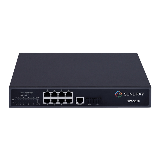
8-Port Gigabit Managed PoE Switch 1.3 交换机面板说明 1.3.1 交换机前面板 交换机的前面板由 8 个 10/100/1000Mbps 的 RJ-45 端口, 2 个千兆 SFP 端口, 1 个 Console 口,1 个复位按钮和一系列 LED 指示灯,如下图 1 所示。 图1 交换机前面板 10/100/1000Mbps 自适应 RJ-45端口(1~8): 交换机的 1~8 端口均支持 10/100/1000Mbps 带宽的设备连接。每个端口对应一组 Link/Act 指示灯。... -
Page 9: 交换机后面板
8-Port Gigabit Managed PoE Switch 图2 LED 指示灯 下表描述了交换机的每个指示灯的详细指示说明。 颜色 状态 状态描述 长亮 通电 电源灯 红色 熄灭 断电 橙色 长亮 对应端口已连接 (10/100Mbps) Link/Act 熄灭 对应端口未连接 (1~8) 绿色 (1000Mbps) 闪烁 对应端口已连接并收发数据 长亮 对应光纤端口已连接 Link/Act 绿色 熄灭 对应光纤端口未连接 (9S~10S) 闪烁 对应光纤端口已连接并收发数据 长亮 对应端口已连接... -
Page 10: 环境参数
8-Port Gigabit Managed PoE Switch 接地柱: 。 位于电源接口右侧,请使用导线接地,以防触电 风扇通风口: 风扇散热口位于交换机后面板的中间位置,用于风扇通风,请勿遮挡。 1.4 环境参数 工作温度:0ºC~45ºC 存储温度:-40ºC~70ºC 工作湿度:10%~90% RH 不凝结 存储湿度:5%~90% RH 不凝结 1.5 物品清单 打开交换机的包装盒,盒内应包括以下产品和附件: 一台 PoE 管理型以太网交换机 一根 AC 电源线 一套安装组件 一本产品用户手册 注:打开产品包装后,若发现以上产品和附件有丢失或损坏,请及时与经销商联系。 产品介绍... -
Page 11: 第二章 安装、使用方法
8-Port Gigabit Managed PoE Switch 第二章 安装、使用方法 2.1 安装交换机 请按照下面的说明进行安装,避免不正确的操作造成设备损坏和安全威胁: 把交换机放置在平稳的地方或桌面上以防跌落摔坏; 确保交换机连接的输入交流电源满足交换机背面标记的电压范围; 为了保持交换机远离电火花,请不要打开交换机的外壳,即使在不通电的情况下; 确保有足够的通风空间给交换机散热; 确保支撑交换机的台面能足够支撑交换机及其配件的重量。 2.1.1 桌面安装 如果用户没有19-英寸的标准机架,那么可以把交换机安装在平稳桌面上。请将附带的橡胶 脚垫安装于交换机底面的四个角上, 然后置于桌面指定位置, 保留足够的通风空间给交换机 散热。 2.1.2 机架式安装 交换机可安装在EIA标准尺寸19-英寸机架中,后者可同其它设备一起置于布线室中。安装 交换机,请遵循以下步骤: 安装时,将安装支架附于交换机的侧面板(一边一个)并用随货提供的螺丝将其固定; 图4 安装支架 然后,用随设备机架提供的螺丝将交换机安装到机架上。 05 ■ 产品安装... -
Page 12: 给交换机上电
8-Port Gigabit Managed PoE Switch 图5 安装到机架 2.1.3 给交换机上电 该交换机是通过交流100~240V 50/60Hz的内部高能效电源供电,请按照以下步骤连接: AC插座: 推荐使用单相三线插座与中性出口或多功能计算机专业的插座。 请确认插座接地线完好且能 正常工作。 AC电源线连接: 用标配的交流电源线一端插入 AC 电源插座,一端接到交换机后面板的电源接口。检查电源 指示灯是否亮,如果电源指示灯亮,表明电源连接成功。 2.2连接计算机(NIC)到交换机 请将网卡插入电脑,安装网卡驱动程序后,请将双绞线的一端连接到您的电脑,另一端将连 接到交换机的任意 RJ-45 口上,交换机和电脑连接距离最大支持 100 米。一旦连接成功, 设备正常上电,则相对应的交换机端口 Link/Act/Speed 状态指示器灯工作。 图 6 连接 PC 到交换机 产品安装 ■ 06... -
Page 13: 连接负载到交换机
8-Port Gigabit Managed PoE Switch 2.3 连接负载到交换机 交换机的 1~8 端口都支持 PoE 供电功能,每个端口的最大输出功率是 30W。您仅需把支持 PoE 供电的受电设备(例如网络电话,网络摄像头,无线终端等)通过网线连接到该交换 机上,交换机就能给此受电设备提供供电。 07 ■ 硬件连接... -
Page 14: 第三章 登录交换机
8-Port Gigabit Managed PoE Switch 第三章 登录交换机 物理安装成功后,您可以使用Web浏览器来配置交换机,监控网络状态和显示统计信息。 3.1 连接到交换机 使用标准的5类或超5类网线(非屏蔽/屏蔽)把交换机和网络设备连接起来,交换机端口会 。 自动适应(MDI / MDI-X、速度、双工)匹配设备进行连接,如下图所示 一旦连接成功,请参阅LED指示灯规格,相对应的交换机端口Link/Act/Speed状态指示灯工 作。 3.2 如何登录交换机 由于交换机提供基于Web的管理登录,您可以手动配置计算机的IP地址,登录到交换机。交 换机的默认设置如下所示。 参数 默认值 默认IP地址 192.168.0.1 默认用户名 admin 默认密码 admin 您可以通过以下步骤登录到交换机的配置窗口: 将交换机连接到计算机的网卡接口; 交换机通上电源; 检查计算机的IP地址是否是该网段中:192.168.0.xxx(“xxx”的范围2~254),如 192.168.0.100; 打开浏览器,输入http://192.168.0.1,然后按“Enter”键。出现交换机登录窗口,如 下图所示; 配置指南 ■ 08... - Page 15 8-Port Gigabit Managed PoE Switch 输入用户名和密码,然后点击“登陆”,就可登录到下面的交换机配置窗口。(可在页 面右上角点击“切换语言”进行语言切换)。 9■ 配置指南...
-
Page 16: 第四章 交换机配置
8-Port Gigabit Managed PoE Switch 第四章 交换机配置 本章描述了如何使用基于网页的管理接口切换交换机软件配置管理功能。 在网页管理界面, 左列显示了配置菜单。 上方可以看到交换机系统信息, 如内存、 软件版本。 最中间一行显示交换机的端口现状。 绿色方块显示端口已连接设备, 而黑色方块显示端口未 连接。配置菜单下方,您可以看到一个工具栏,可进行端口信息、流量走势、设备配置、端 口统计信息查看。 4.1 快速配置 在导航栏中选择“快速配置”,可在此模块中创建 VLAN、将端口加入 VLAN 中、设置交换 机基本信息以及修改登录密码。如下图: 配置指南■ 10... - Page 17 8-Port Gigabit Managed PoE Switch 【参数说明】 参数 描述 VLAN 号,8GE 默认 VLAN 1 VLAN ID VLAN 名称 VLAN 的标示 VLAN IP 地址 管理此 VLAN 的 ip 地址 设备名称 交换机名称 管理 VLAN 交换机管理使用 VLAN 【使用指导】 Native VLAN:作为 Trunk,这个口要属于一个 Native VLAN。所谓 Native VLAN,就是指 在这个接口上收发的...
- Page 18 8-Port Gigabit Managed PoE Switch 2) 点击“下一步”按钮,进入其他设置,如:将管理 ip 地址改为 192.168.0.12,设备名称 改为 switch-123,默认网关及 dns 服务器设置为 172.16.1.241。 用 192.168.0.12 进行登录,选择密文密码,设置新密码为 1234。 配置指南■ 12...
-
Page 19: 端口管理
8-Port Gigabit Managed PoE Switch 4.2 端口管理 在导航栏选择“端口管理”,您可以进行基本设置、端口聚合、端口镜像、端口限速和端 口隔离等设置。 4.2.1 基本设置 在导航栏中选择“端口管理>基本设置”,可对面板上端口进行端口描述、端口速率、端口 状态、工作模式、流量控制、交叉线序配置,如下图: 【参数说明】 参数 描述 端口 选择当前配置端口号 13■ 配置指南... -
Page 20: 端口聚合
8-Port Gigabit Managed PoE Switch 端口状态 选择是否关闭链路端口 流量控制 是否开启流控 可选以下几种: 自动协商 端口速率 10 M 100 M 1000 M 可选择模式有以下几种: 自动协商 工作模式 半双工 全双工 端口描述 对端口进行描述 可选择模式有以下几种: 自动协商 交叉线序 MDIX 【使用指导】 开启流量控制需将自协商关闭, 自协商关闭就是设置端口速率及工作模式; 将端口速率设置 超过端口实际速率,端口将掉线。 【配置举例】 如:将端口设置为 10M、半双工、开启流量控制及端口状态、设置交叉线序为自协商。 4.2.2 端口聚合 在导航栏中选择“端口管理>端口聚合”,可将多个物理口绑定到一个逻辑口来扩充端口带 宽或实现带宽的冗余备份,如下图:... -
Page 21: 端口镜像
8-Port Gigabit Managed PoE Switch 【参数说明】 参数 描述 聚合端口 8GE 交换机可设置 8 个链路汇聚组,group_1 到 group_8 成员端口 为每个组添加自己的成员端口,且不能和其他组的成员重合 【使用说明】 开启 ARP 检查功能的端口、重要设备 ARP 欺骗的端口、设置 Mac VLAN 功能的端口及端 口镜像中的监控端口无法加入聚合! 【配置举例】 如:设置端口 7、8 为聚合端口 1,可让此聚合端口 1 与其他交换机聚合端口 1 相连来搭建 交换机链路。 4.2.3 端口镜像 在导航栏选择“端口管理>端口镜像”,可将一个或多个源端口报文复制一份转发到一个目 的端口中,如下图:... - Page 22 8-Port Gigabit Managed PoE Switch 【参数说明】 参数 描述 源端口 对该端口的出入流量进行监管 目的端口 设置目的端口,将源端口的流量数据进行复制转发到报文分析器 分析报文情况转发给目的端口 镜像组 范围 1-4 【使用说明】 已加入聚合口的端口不能作为目的端口和源端口, 目的端口和源端口不能为同一个。 页面上 配置后默认是对源端口出入流量进行监管。 【配置举例】 如:设置一镜像组用于端口 6 监管端口 2、3、4、5 端口出入流量情况。 配置指南■ 16...
-
Page 23: 端口限速
8-Port Gigabit Managed PoE Switch 4.2.4 端口限速 在导航栏选择“端口管理>端口限速”,可对端口输出、输入限速,如下图: 【参数说明】 参数 描述 输入限速 设置端口输入的速度 输出限速 设置端口输出的速度 【使用说明】 1 Mbit/s = 1000 Kbit/s = 1000 / 8 KB/s = 125 KB/s 。 即 1M 带宽对应的理论速率是 125KB/s 。 【配置举例】 如:将端口 4 输入速率设置为 6400 kb/s,将输出速率设置为 3200 kb/s。 17■... -
Page 24: 广播风暴
8-Port Gigabit Managed PoE Switch 4.2.5 广播风暴 在导航栏选择“端口管理>广播风暴”,可对端口进行风暴控制,如下图: 【参数说明】 参数 描述 广播抑制值 广播数据包的风暴抑制值 组播抑制值 组播数据包的风暴抑制值 单播抑制值 单播数据包的风暴抑制值 未知名:以组播组中不存在的 ip 为目的地址的流。 Multicast 类型包 知名及不知名:任一组播流。 未知名:设备 MAC 表中没有该单播帧的目的 MAC 条目。 Unicast 类型包 知名及不知名:任一单播流。 配置指南■ 18... -
Page 25: 端口隔离
8-Port Gigabit Managed PoE Switch 【使用说明】 1 Mbit/s = 1000 Kbit/s = 1000 / 8 KB/s = 125 KB/s 。 即 1M 带宽对应的理论速率是 125KB/s 。 【配置举例】 如:需将转发到端口 1-8 的各种包转发速率为 5000 kb/s,组播类型包设置为知名及不知名, 单播类型包设置仅未知包。 4.2.6 端口隔离 在导航栏选择“端口管理>端口隔离”,可设置端口相互隔离,如下图: 【参数说明】 参数 描述 源端口 选择一个端口,以配置隔离端口 隔离端口... -
Page 26: 端口信息
8-Port Gigabit Managed PoE Switch 已加入聚合口的端口也能作为目的端口和源端口,目的端口和源端口不能为同一个。 【配置举例】 如:将端口 3、4、5、6 相互隔离。 配置成功后,端口 3/4/5/6 相互隔离。 4.2.7 端口信息 在导航栏选择“端口管理>端口隔离”,可查询端口信息,如下图: 【参数说明】 参数 描述 输入流量 统计端口输入流量 输出流量 统计端口输出流量 配置指南■ 20... -
Page 27: Vlan管理
8-Port Gigabit Managed PoE Switch 【使用说明】 显示端口的输入和输出流信息端口的连接状态,所属 VLAN。 【配置举例】 如:输入端口号 1 进行查询。 4.3 VLAN管理 在导航栏选择“VLAN 管理”,您可以进行 VLAN 管理、Trunk 口设置和 Hybrid 口设置等 设置。 4.3.1 VLAN 设置 在导航栏中选择“VLAN 管理”,可创建 VLAN 并将端口设置到 VLAN 中(端口默认状态 为 access 模式),如下图: 【参数说明】 参数 描述 VLAN 号,8GE 默认 VLAN 1 VLAN ID VLAN 名称... -
Page 28: Trunk 口设置
8-Port Gigabit Managed PoE Switch 可点击页面操作中编辑、删除按钮进行相应操作。 4.3.2 Trunk 口设置 在导航栏中选择“VLAN 管理>Trunk 口设置”,可将端口设置为 Trunk 口 【参数说明】 参数 描述 只可设置一个 Native VLAN 允许通过的 VLAN 可设置多个 【使用指导】 Native VLAN:作为 Trunk,这个口要属于一个 Native VLAN。所谓 Native VLAN,就是指 在这个接口上收发的 UNTAG 报文,都被认为是属于这个 VLAN 的。显然,这个接口的缺 省 VLAN ID (即 IEEE 802.1Q 中的 PVID) 就是 Native VLAN 的 VLAN ID。 同时, 在 Trunk 上发送属于... -
Page 29: Hybrid 口设置
8-Port Gigabit Managed PoE Switch 这个 Trunk 口。 【配置举例】 如:PVID=VLAN2 PC1:192.168.0.2,端口 8, access VLAN2。 PC2:192.168.0.3,端口 7, Trunk allowed VLAN 1-2。 PC3:192.168.0.4,端口 6, access VLAN1(默认下端口属于 VLAN1)。 让 PC2 能 PING 通 PC1,不能 PING 通 PC3。 4.3.3 Hybrid 口设置 在导航栏中选择 “VLAN 管理>Hybrid 口设置” , 可将端口设置为带 tag 和不带 tag 的 Hybrid 口,如下图:... - Page 30 8-Port Gigabit Managed PoE Switch Hybrid 端口收报文: 收到一个报文,判断是否有 VLAN 信息:如果没有则打上端口的 PVID,并进行交换转发,如 果有则判断该 Hybrid 端口是否允许该 VLAN 的数据进入:如果可以则转发,否则丢弃(此时 端口上的 untag 配置是不用考虑的,untag 配置只对发送报文时起作用)。 Hybrid 端口发报文: 1、判断该 VLAN 在本端口的属性(disp interface 即可看到该端口对哪些 VLAN 是 untag, 哪些 VLAN 是 tag)。 2、如果是 untag 则剥离 VLAN 信息,再发送,如果是 tag 则直接发送。 【配置举例】...
-
Page 31: 故障/安全
8-Port Gigabit Managed PoE Switch 装 VLAN20 的标记后送入交换机,交换机发现 inter e0/1 允许 VLAN 20 的数据通过,于是 数据被转发到 inter e0/1 上,由于 inter e0/1 上 VLAN 20 是 untagged 的,于是交换机此时 去除数据包上 VLAN20 的标记, 以普通包的形式发给 pc1, 此时 pc2->pc1 走的是 VLAN20。 4.4 故障/安全 在导航栏选择“故障/安全”,您可以进行防攻击、通路检测、ACL 访问控制和 802.1x 等 设置。... - Page 32 8-Port Gigabit Managed PoE Switch 校验失败时,报文将被丢弃。 将在 DHCP 请求报文中添加 option82 信息,转发给服务器, Option82 使能 DHCP 服务器可根据该选项信息进行灵活的地址分配。 开启使能情况下会保留客户端的 option82 选项,并转发报文, 而关闭使能情况下, 如果收到客户端发来的带 option82 的 DHCP 客户端 option82 使能 报文时,将丢弃该报文。 依据 DHCP 报文所走的 vlan 选择使用该 vlan 下所配置的电路 ID 子选项内容, 如果没有配置的话, 默认使用 circuit id 为 0 类型的, 内容为...
- Page 33 8-Port Gigabit Managed PoE Switch 4.效验源 mac F0:DE:F1:12:98:D2,将服务器设置为 192.168.0.1。 5.设置 option82 信息。 27■ 配置指南...
-
Page 34: 防 Dos 攻击
8-Port Gigabit Managed PoE Switch 6.将端口 7 进行绑定。 4.4.1.2 防 DOS 攻击 在导航栏中选择“故障/安全> 防攻击>防 DOS 攻击”,开启防 DOS 攻击功能,拦截 Land 攻击报文、非法 TCP 报文,确保设备或服务器主机向合法用户提供正常的服务,如下图: 【使用说明】 开启防 DOS 攻击功能,拦截 Land 攻击报文、非法 TCP 报文,确保设备或服务器主机向合 法用户提供正常的服务。 【配置举例】 如:开启防 DOS 攻击。 4.4.1.3 IP 源防护 在导航栏中选择“故障/安全> 防攻击>IP 源防护”,通过源防护端口使能,可以对端口转 发的报文进行过滤控制,防止非法报文通过端口,从而限制了对网络资源的非法使用,提高... -
Page 35: 三元绑定
8-Port Gigabit Managed PoE Switch 添加当前正在使用的端口作为 IP 源防护使能端口, 端口将无法使用。 可以对用户进行基于 IP+MAC+VLAN+Port 的检测, IP Source Guard 无法在 DHCP Snooping 的信任端口上开 启。 【配置举例】 如:需先将 ip 源防护使能端口打开,再进行绑定。 4.4.1.4 三元绑定 自动探测出基于端口的 IP 地址, 在导航栏中选择“故障/安全> 防攻击>三元绑定”, mac 地址的映射关系,然后实现一键绑定的功能 ,如下图: 29■ 配置指南... - Page 36 8-Port Gigabit Managed PoE Switch 【使用说明】 一键绑定之前一定要将绑定使能开关打开,并且若要访问交换机应绑定与交换机同网段的 IP 地址。ARP 检测防私有静态 IP 地址时,静态表项 IP+MAC+Port。 【配置举例】 如:需将先绑定使能开启,一键绑定端口 7。 可勾选删除选项。 配置指南■ 30...
-
Page 37: 通路检测
8-Port Gigabit Managed PoE Switch 4.4.2 通路检测 4.4.2.1 ping 检测 在导航栏中选择“故障/安全> 通路检测”,可查看是否可 ping 通此 ip 地址,如下图: 【参数说明】 参数 描述 目的 ip 地址 填入需检测的 ip 地址 超时时间 范围 1-10 重复次数 检测次数 【使用说明】 使用 ping 功能检测网络连接及主机是否可达。 【配置举例】 如:PING 连接 pc 的 ip 地址。 31■... -
Page 38: Tracert 检测
8-Port Gigabit Managed PoE Switch 4.4.2.2 tracert 检测 在导航栏中选择“故障/安全> 通路检测>tracert”,可以检测出到目的地所经过的网关, 如下图: 【参数说明】 参数 描述 目的 ip 地址 填入需检测的 ip 地址 超时时间 范围 1-10 【使用说明】 该功能用于检测目的地是否可达及到达目的地的路径,如果目的地不可达,诊断出问题点。 【配置举例】 如:检测目的 ip192.168.0.64。 4.4.2.3 线缆检测 在导航栏中选择“故障/安全> 通路检测>线缆检测”,可以检测连接设备状态,如下图: 【使用说明】 检测结果中程度表示线缆状态非正常时距离故障点的长度(检测结果存在 5 米范围内的偏 配置指南■ 32... -
Page 39: Acl 访问控制
8-Port Gigabit Managed PoE Switch 差)。 【配置举例】 4.4.3 ACL 访问控制 在导航栏中选择 “故障/安全>ACL 访问控制” , 可应用 ACL 规则到端口中并设置生效时间: 【参数说明】 参数 描述 目的 ip 地址 填入需检测的 ip 地址 超时时间 范围 1-10 【使用说明】 ACL 规则是有先后顺序的,排在前面的规则会优先匹配。如果策略条目很多,操作时间会 相对变长。 基本原则: 1、按顺序执行,只要有一条满足,则不会继续查找。 2、隐含拒绝,如果都不匹配,那么一定匹配最后的隐含拒绝条目,思科默认的。 3、任何条件下只给用户能满足他们需求的最小权限。 4、不要忘记把 ACL 应用到端口上。 33■... - Page 40 8-Port Gigabit Managed PoE Switch 【配置举例】 如:测试生效时间为星期一到星期五每天 9 点到 18 点,设置端口 3 不能访问网络。 步骤:建 ACL 生效时间--建 ACL 规则--应用到端口。 配置指南■ 34...
- Page 41 8-Port Gigabit Managed PoE Switch 4.4.4 802.1x 在导航栏中选择“故障/安全>802.1x”,可以在此处配置 802.1x 认证。 【参数说明】 参数 描述 重认证周期 设置重认证周期的时间,取值范围在 60~7200S 之间 认证重传最大次数 选择认证重传最大次数,取值范围在 1~10 之间 认证失败 vlan 次数 选择认证失败 Vlan 次数,取值范围在 1~3 之间 【使用说明】 802.1X 是基于客户机/服务器的访问控制和认证协议。它可以限制未经授权的用户或设备 连接到端口访问 LAN / WLAN。 【配置举例】 步骤:开启 802.1x 功能--应用到端口。 如:...
-
Page 42: Poe 管理
8-Port Gigabit Managed PoE Switch 4.5 POE 管理 在导航栏选择“POE 管理”,您可以进行 POE 管理、POE 配置和 POE 延迟等设置。 4.5.1 POE 管理 4.5.1.1 高级管理 在导航栏选择“POE 管理>高级管理”,可查看 POE 状态信息及设置配置。如下图: 【参数说明】 参数 描述 供电模式 选择 PSE 供电的模式 告警功率 配置的告警门限 配置指南■ 36... -
Page 43: 温度配置
8-Port Gigabit Managed PoE Switch 保留功率 配置保留功率 告警通告 配置告警通告状态, 【使用说明】 实际应用中需要控制系统在功率变化和端口上下电时是否进行发送 trap 通告。 接收 Trap 通告需将 Snmp 开启,并设置 trap 目标主机。 【配置举例】 如:将告警通告设置为 120W,开启告警通告。 4.5.1.2 温度配置 在导航栏选择“POE 管理>高级管理”,可设置 POE 芯片的告警阀值。如下图: 【参数说明】 参数 描述 配置温度告警门限,范围 70-149 告警阈值 【使用说明】 接收 Trap 通告需将 Snmp 开启,并设置 trap 目标主机。 【配置举例】... -
Page 44: Poe 端口配置
8-Port Gigabit Managed PoE Switch 4.5.2 POE 端口配置 在导航栏选择“POE 管理>POE 配置”,可对端口 POE 进行设置。如下图: 【参数说明】 参数 描述 最大功率 选择配置的端口的最大功率 使能 选择配置的使能状态 优先级 配置端口的优先级,当负载超过 POE 最大功率时,优先级低的 端口下设备将先掉线 检测模式 配置端口的检测模式 【使用说明】 接收 Trap 通告需将 Snmp 开启,并设置 trap 目标主机。 【配置举例】 如:将 8 口的端口使能打开,设置最大功率为 23 W、检测模式为 AF、优先级为高。 配置指南■... -
Page 45: Poe 延迟
8-Port Gigabit Managed PoE Switch 4.5.3 POE 延迟 在导航栏选择“POE 管理>POE 延迟”,可对端口 POE 延迟进行设置。如下图: 【参数说明】 参数 描述 重启时间段 设置端口重启的时间 端口延迟时间 设置端口延迟时间 【使用说明】 接收 Trap 通告需将 Snmp 开启,并设置 trap 目标主机。 【配置举例】 如:设置端口 1 的 POE 重启时间为每天的 9:57:33,端口延迟时间为 20 秒。 39■ 配置指南... -
Page 46: Stp
8-Port Gigabit Managed PoE Switch 4.6 STP 在导航栏选择“STP”,您可以进行 MSTP 域和 STP 桥/端口等设置。 4.6.1 MSTP 域 在导航栏选择“STP>MSTP 域”,可修改域及域名,添加实例映射到 VLAN。如下图: 【参数说明】 参数 描述 域名 配置域的名称 修订级别 配置修订级别参数 实例 ID 选择配置实例 ID 号 配置实例映射的 VLAN VLAN ID 【使用说明】 一个实例只能映射到一个 VLAN,实例和 VLAN 是一一对应的关系。 配置指南■ 40... -
Page 47: Stp 桥/端口
8-Port Gigabit Managed PoE Switch 【配置举例】 如: 将域改为 DEADBEEF0102,修订级别为 123,实例 4 映射到 VLAN 2 中,需先创 建 VLAN 2。 4.6.2 STP 桥/端口 在导航栏选择“STP>STP 桥/端口”,可对桥、端口进行相关配置,如下图: 【参数说明】 参数 描述 实例优先级 是否开启实例优先级设置 实例 ID 选择已创建的实例 id 进行配置 使能 是否开启桥 STP 功能 桥优先级 设置桥实例优先级,默认桥实例优先级为 32768 模式... - Page 48 8-Port Gigabit Managed PoE Switch 倍数,范围 0-240 链路开销 auto or 1-200000000,用以决定各端口到根的路径 花费 快速端口 PortFast 功能能够使得二层接入端口立即进入 Forwarding 状态 自动边缘 边缘端口的自动识别。边缘端口是指不直接与任何 交换机连接,也不通过端口所连接的网络间接与任 何交换机相连的端口。 点对点 配置接口的连接类型是不是“点对点连接” Bpdu 保护 开启该功能能够防止攻击者在直连终端的端口上发 送 BPDU 导致网络震荡 Bpdu 过滤 开启 BPDU Filter 功能,将强制端口不参与生成树 计算,端口不接收也不向外发送 BPDU 报文。 兼容性模式 根 据 当 前 端 口 的 接 口 属 性 信 息 有 选 择 性 的 携 带 MSTI 的信息进行发送,...
- Page 49 8-Port Gigabit Managed PoE Switch 2)设置已上线端口 mstp 配置,选择已创建的实例,设置优先级(配置未上线的端口,需 上线配置才会生效,才可点击“查看当前配置”按钮进行查看到已配置完成的)。 43■ 配置指南...
-
Page 50: Dhcp中继
8-Port Gigabit Managed PoE Switch 4.7 DHCP中继 在导航栏选择“DHCP 中继”,您可以进行 DHCP 中继和 option82 等设置。 4.7.1 DHCP 中继 开启 DHCP 中继功能,设置和查看中继服务器 IP 在导航栏选择“DHCP 中继”,可 地址及其状态 。如下图: 【参数说明】 参数 描述 IP 地址 DHCP 服务器地址 状态 生效和不生效 DHCP 中继使能 开启和关闭 DHCP 中继代理功能 开启时,当收到的客户端 DHCP 报文带 option82 信息时,保留, DHCP option 信任... -
Page 51: Option82
8-Port Gigabit Managed PoE Switch 4.7.2 Option82 OPTION82 代理电路、代理远程、 在导航栏选择“DHCP 中继>Option82”,可设置 ip 地址 。如下图: 【参数说明】 参数 描述 DHCP 请求报文所在 VLAN,取值范围为 1~4094 VLAN id 电路控制 依据 DHCP 报文所走的 vlan 选择使用该 vlan 下所配置的电路 ID 子选项内容,如果没有配置的话,默认使用 circuit id 为 0 类型的,内容为 VLAN ID + interface number,即 DHCP 客户 端所在... -
Page 52: Dhcp 服务器
8-Port Gigabit Managed PoE Switch 4.8 DHCP 服务器 设置 DHCP 服务器使能、 DHCP 地址池、 Option、 在导航栏选择 “DHCP 服务器” , 可 绑定表、缺省网关配置、DNS 服务器配置 。如下图: 4.8.1 DHCP 服务器使能 在导航栏选择“DHCP 服务器>DHCP 服务器使能”,可在此开启或关闭 DHCP 服务器。 如下图: 配置指南■ 46... -
Page 53: Dhcp 地址池
8-Port Gigabit Managed PoE Switch 【使用说明】 开启 DHCP 服务器时必须先关闭 DHCP 中继功能。 【配置举例】 如:开启 DHCP 服务器。 4.8.2 DHCP 地址池 在导航栏选择“DHCP 服务器>DHCP 地址池”,可在此设置 DHCP 地址池。如下图: 【参数说明】 参数 描述 地址池 ID 设置地址池 ID 号范围在 1 ~ 65535 之间 子网 IP 设置子网 IP 地址,子网 IP 和开始 IP 需要在同一网段 子网掩码... - Page 54 8-Port Gigabit Managed PoE Switch 【配置举例】 如:设置地址池为 1,域名为 work,子网 IP 为 192.168.1.5,子网掩码为 255.255.255.0, 开始 IP 为 192.168.1.100,结束 IP 为 192.168.1.199,租约时间为 1 天。 4.8.3 Option 在导航栏选择“DHCP 服务器>Option”,可在此设置 DHCP 服务器的 Option。如下图: 【参数说明】 参数 描述 地址池 ID 选择要配置地址池的 ID 代码 设置代码的值 代码值类型 可以选择以下几种类型: ASCII 代码值...
-
Page 55: 绑定表
8-Port Gigabit Managed PoE Switch 4.8.4 绑定表 在导航栏选择“DHCP 服务器>地址表”,你可以在此查看或删除绑定的地址信息。如下图: 4.8.5 缺省网关配置 在导航栏选择“DHCP 服务器>缺省网关配置”,你在此设置缺省网关。如下图: 【使用说明】 根据地址池的 ID 设置 DHCP 服务器的缺省网关。 【配置举例】 如:选择地址池 ID 为 1,设置网关为 192.168.1.55。 4.8.6 DNS 服务器配置 在导航栏选择“DHCP 服务器>DNS 服务器配置”,你在此设置 DNS 服务器。如下图: 49■ 配置指南... -
Page 56: Tacacs
8-Port Gigabit Managed PoE Switch 【使用说明】 根据地址池的 ID 设置 DHCP 服务器的 DNS 服务器。 【配置举例】 如:选择地址池 ID 为 1,设置网关为 47.54.89.210。 4.9 TACACS+ 在导航栏选择“TACACS+>TACACS+配置”,你在此设置 TACACS+认证相关配置。 【使用说明】 对 TACACS+服务器参数设置。 【配置举例】 如:对全局和端口进行配置,设置服务器超时时长为 5,服务器重试次数为 3,会话/连接 模式为 Multi,密匙为 2644as 服务器 IP 为 192.168.0.88,认证端口为 49。 配置指南■ 50... -
Page 57: Radius
8-Port Gigabit Managed PoE Switch 4.10 RADIUS 在导航栏选择“RADIUS”,你在此设置 RADIUS 认证相关配置。 4.10.1 RADIUS 配置 在导航栏选择“RADIUS>RADIUS 配置”,你在此设置 RADIUS 认证全局相关配置。 【使用说明】 对 RADIUS 服务器全局参数设置。 【配置举例】 如:设置 RADIUS 服务器重传次数为 3,服务器超时时间为 2,服务器静默时间为 200, Dead-criteria 重试次数为 3,Dead-criteria 超时时间为 5。 51■ 配置指南... -
Page 58: Radius 服务器配置
8-Port Gigabit Managed PoE Switch 4.10.2 RADIUS 服务器配置 在导航栏选择“RADIUS>RADIUS 服务器配置”,你在此设置 RADIUS 服务器相关配置。 【使用说明】 对 RADIUS 服务器全局参数设置。 【配置举例】 如:设置服务器地址为 192.168.0.68,认证端口和密匙为默认,开启主动探测并设置测试 名称我 test,空闲时间为 3。 4.11 AAA 你在此设置AAA使能,域,服务器组,AAA认证相关配 在导航栏选择“AAA”, 置。如下图所示: 配置指南■ 52... -
Page 59: Aaa 使能配置
8-Port Gigabit Managed PoE Switch 4.11.1 AAA 使能配置 在导航栏选择“AAA>AAA 使能配置”,你在此开启或关闭 AAA 使能。如下图所示: 【使用说明】 开启或关闭 AAA 使能,默认为开启状态。 【配置举例】 如:关闭 AAA 使能。 4.11.2 域配置 在导航栏选择“AAA>域配置”,你在此设置域使能的相关参数。如下图所示: 53■ 配置指南... -
Page 60: 服务器组配置
8-Port Gigabit Managed PoE Switch 【使用说明】 开启或关闭域使能,默认为开启状态,设置域使能相关参数。 【配置举例】 如:开启域使能--设置 ISP 域。 4.11.3 服务器组配置 在导航栏选择“AAA>服务器组配置”,你在此设置多个服务器的相关参数。如下图所示: 配置指南■ 54... -
Page 61: Aaa 认证配置
8-Port Gigabit Managed PoE Switch 【使用说明】 设置服务器的相关参数。 【配置举例】 如: 1. 设置服务器的相关参数。 2. 删除服务器。 4.11.4 AAA 认证配置 在导航栏选择“AAA>AAA 认证配置”,你在此设置 AAA 认证的 Login 认证,Enable 认 证,Dot1x 认证。如下图所示: 4.11.4.1 Login 认证 在导航栏选择“AAA>AAA 认证配置>Login 认证”,在此你可以设置 Login 认证的方法。 如下图所示: 55■ 配置指南... - Page 62 8-Port Gigabit Managed PoE Switch 【参数说明】 参数 描述 第一方法 可以选择以下几种类型: 本地服务器组 Radius 服务器组 TACACS+服务器组 自定义服务器组 无 第二方法 可以选择以下几种类型: 本地服务器组 Radius 服务器组 TACACS+服务器组 自定义服务器组 无 第三方法 可以选择以下几种类型: 本地服务器组 Radius 服务器组 TACACS+服务器组 自定义服务器组 无 第四方法 可以选择以下几种类型: 本地服务器组 Radius 服务器组 TACACS+服务器组 自定义服务器组 无 【使用说明】...
-
Page 63: Enable 认证
8-Port Gigabit Managed PoE Switch 服务器组,第三方法为 TACACS+服务器组,第四方法为自定义服务器组。 4.11.4.2 Enable 认证 在导航栏选择 “AAA>AAA 认证配置>Enable 认证” , 在此你可以设置 Enable 认证的方法。 如下图所示: 【参数说明】 参数 描述 第一方法 可以选择以下几种类型: 本地服务器组 Radius 服务器组 TACACS+服务器组 自定义服务器组 无 第二方法 可以选择以下几种类型: 本地服务器组 Radius 服务器组 TACACS+服务器组 自定义服务器组 无 57■ 配置指南... -
Page 64: Dot 1X 认证
8-Port Gigabit Managed PoE Switch 第三方法 可以选择以下几种类型: 本地服务器组 Radius 服务器组 TACACS+服务器组 自定义服务器组 无 第四方法 可以选择以下几种类型: 本地服务器组 Radius 服务器组 TACACS+服务器组 自定义服务器组 无 【使用说明】 设置 Enable 认证的方法。 【配置举例】 如:选择域名为 None,钩选 Enable 认证,设置第一方法为本地服务器组,第二方法为 Radius 服务器组,第三方法为 TACACS+服务器组,第四方法为自定义服务器组。 4.11.4.3 Dot 1x 认证 在导航栏选择“AAA>AAA 认证配置>Dot 1x 认证”,在此你可以设置 Dot 1x 认证的方法。 如下图所示:... - Page 65 8-Port Gigabit Managed PoE Switch 【参数说明】 参数 描述 第一方法 可以选择以下几种类型: 本地服务器组 Radius 服务器组 TACACS+服务器组 自定义服务器组 无 第二方法 可以选择以下几种类型: 本地服务器组 Radius 服务器组 TACACS+服务器组 自定义服务器组 无 第三方法 可以选择以下几种类型: 本地服务器组 Radius 服务器组 TACACS+服务器组 自定义服务器组 无 第四方法 可以选择以下几种类型: 本地服务器组 Radius 服务器组 TACACS+服务器组 自定义服务器组 无 【使用说明】...
-
Page 66: Qos管理
8-Port Gigabit Managed PoE Switch Radius 服务器组,第三方法为 TACACS+服务器组,第四方法为自定义服务器组。 4.12 QoS管理 在导航栏选择“QoS 管理”,您可以进行队列设置和映射队列等设置。 4.12.1 队列设置 在导航栏选择“QoS>队列设置”,可设置队列的调度策略。如下图: 【参数说明】 参数 描述 调度策略 可选择 4 种模式:RR 循环调度 SP 绝对优先级调度 WRR 加权循环调度 WFQ 加权公平调度 配置指南■ 60... -
Page 67: 映射队列
8-Port Gigabit Managed PoE Switch WRR 权值 设置每个队列权值,他们将按比例占用带宽发送数据 【使用说明】 队列 7 不能为 0. 【配置举例】 如:将调度策略设置为 WRR,权重值分别为 10、11、12、12、14、15、16、17。 4.12.3 映射队列 4.12.3.1 服务类别到队列映射 在导航栏选择“QoS>映射队列”,可将服务类别映射到相对应的队列。如下图: 【参数说明】 参数 描述 服务 ID 即 VLAN 的优先级 COS 字段(0-7) 队列 ID 设置每个 COS 值映射的队列序号(0-7) 【配置举例】 如:将 cos 3 映射到队列 7,将队列 7 的权值设置为 10。 61■... -
Page 68: 差分服务到服务类别映射
8-Port Gigabit Managed PoE Switch 4.12.3.2 差分服务到服务类别映射 在导航栏选择“QoS>映射队列>差分服务到服务类别映射”,可将差分服务映射到相对应 的服务类别。如下图: 【参数说明】 参数 描述 服务列表 dscp 字段有 7 位(0-63) 分为 4 个表 队列 ID 将 DSCP 映射到 COS 字段(0-7),在根据 COS 映射到 的队列 【使用说明】 Cos 优先级大于 dscp,dscp 优先级大于端口。 【配置举例】 如:将 dscp 值为 3、12、23 的全部映射到 cos5。 配置指南■... -
Page 69: 端口到服务类别映射
8-Port Gigabit Managed PoE Switch 4.12.3.3 端口到服务类别映射 在导航栏选择“QoS>映射队列>差分服务到服务类别”,可将端口映射到相对应的服务类 别。如下图: 【参数说明】 参数 描述 端口 选择端口号(0-8) 服务 ID 映射到服务 ID,然后根据服务 ID 进入队列 【使用说明】 Cos 优先级大于 dscp,dscp 优先级大于端口。 【配置举例】 如:将端口 4、5、6 分别映射到 cos4、cos5、cos6。 63■ 配置指南... -
Page 70: 地址表
8-Port Gigabit Managed PoE Switch 4.13 地址表 在导航栏选择“地址表”,您可以进行 MAC 添加和删除、MAC 学习和老化和 MAC 地址 过滤等设置。 配置指南■ 64... -
Page 71: Mac 添加与删除
8-Port Gigabit Managed PoE Switch 4.13.1 Mac 添加与删除 在导航栏选择“地址表>Mac 添加与删除”,可添加静态 Mac 及删除 Mac 并查看到当前的 Mac 地址表。如下图: 【参数说明】 参数 描述 清除 Mac 可选择清除多播 Mac 地址、清除动态单播 Mac 地址、清除静态 单播 Mac 地址、清除指定 Mac 地址、清除 Mac 地址表 填入需添加或删除的 VLAN id, 未创建的 VLAN 需创建才可生效 VLAN 【使用说明】... -
Page 72: Mac 学习和老化
8-Port Gigabit Managed PoE Switch 【配置举例】 如:1)将端口 6 Mac 设置为静态的 Mac。 2)清除端口 6 静态的 Mac 地址。 4.13.2 Mac 学习和老化 在导航栏选择“地址表>Mac 学习和老化”,可设置端口下 Mac 最大学习数及 Mac 地址老 化时间。如下图: 【参数说明】 参数 描述 Mac 地址学习限制 范围 0-8191,默认为 8191 Mac 地址老化时间 默认下为 300 【使用说明】 配置指南■ 66... -
Page 73: Mac 地址过滤
8-Port Gigabit Managed PoE Switch 根据不同的条件清除 Mac 地址,查看/添加/学习 Mac 地址,Mac 地址过滤。 【配置举例】 如:1)设置端口 5、6、3、4 最大学习数为 3000。 2)将端口设备掉线或学习到的 Mac 地址过 2 分钟后从 Mac 地址表中自动消失。 4.13.3 Mac 地址过滤 在导航栏选择“地址表>Mac 地址过滤”,可根据条件过滤过不需要的 Mac 地址。如下图: 【参数说明】 参数 描述 Mac 地址 不能添加组播的 Mac 地址 VLAN 号 VLAN 【使用说明】... -
Page 74: Snmp管理
8-Port Gigabit Managed PoE Switch 4.14 Snmp管理 在导航栏选择“Snmp 管理”,您可以进行 Snmp 配置和 Rmon 配置等设置。 4.14.1 Snmp 配置 4.14.1.1 Snmp 配置 在导航栏选择“Snmp 管理>Snmp 配置”,可 Snmp 功能开启关闭。如下图: 【使用说明】 在配置 Rmon 的时候 Snmp 功能必须开启,否则会配置失败。 【配置举例】 如:开启 Snmp。 4.14.1.2 团体 在导航栏选择“Snmp 管理>Snmp 配置>团体”,可指定团体的访问权限。如下图: 配置指南■ 68... - Page 75 8-Port Gigabit Managed PoE Switch 【参数说明】 参数 描述 团体名称 团体字符串,相当于 NMS 和 Snmp 代理之间的通信密码 访问权限 只读:指定 NMS(Snmp 主机)对 MIB 的变量只能读,不能修 改 只读可写:指定 NMS(Snmp 主机)对 MIB 的变量只能读,也 可修改 【使用说明】 团体配置数量上限为 8。 【配置举例】 如:添加一条名为 public 的可读写团体。 4.14.1.3 视图 在导航栏选择“Snmp 管理>Snmp 配置>视图”,设置视图规则来允许或禁用对某些 MIB 对象的访问。如下图:...
- Page 76 8-Port Gigabit Managed PoE Switch 【配置举例】 如:建立视图 123、将 MIB 子树 oid 1.3.6.1 包含其中。 4.14.1.4 组 在导航栏选择“Snmp 管理>Snmp 配置>组”,设置 Snmp 用户组。如下图: 【参数说明】 参数 描述 组名称 用户组名 安全级别 只认证不加密:该组的用户传输的消息需要验证但数据不需要保 密 不认证不加密:该组用户传输的消息不需要验证数据也不需要保 密 既认证又加密:该组用户传输的消息需要验证同时传输的数据需 要保密 只读视图、读写视图、 关联的视图名 通知视图 【使用说明】 组配置数量上限为 8,新建组之前需新建视图才可创建组。 【配置举例】 如:先新建视图 123,再新建组 goup1。 配置指南■...
- Page 77 8-Port Gigabit Managed PoE Switch 4.14.1.5 用户 在导航栏选择“Snmp 管理>Snmp 配置>用户”,设置 Snmp 用户。如下图: 【参数说明】 参数 描述 组名称 用户名,范围 1-16 安全级别 只认证不加密: 该组的用户传输的消息需要验证但数据不需要保 密 不认证不加密: 该组用户传输的消息不需要验证数据也不需要保 密 既认证又加密: 该组用户传输的消息需要验证同时传输的数据需 要保密 认证模式 指定使用 MD5 认证协议或 SHA 认证协议 认证密码 范围 8-60 加密模式 指定使用 AES 加密协议或 DES 加密协议 组名称...
-
Page 78: Trap
8-Port Gigabit Managed PoE Switch 4.14.1.6 Trap 在导航栏选择“Snmp 管理>Snmp 配置>Trap”,可指定发送陷阱消息的 Snmp 主机 (NMS) 。如下图: 【参数说明】 参数 描述 目的 ip 地址 Snmp 主机 ipv4 地址 安全名称 Snmp 用户名 安全模式 V1、V2、V3 认证密码 范围 8~60 字符 加密模式 指定使用 AES 加密协议或 DES 加密协议 组名称 用户组名... -
Page 79: Rmon 配置
8-Port Gigabit Managed PoE Switch 4.14.2 Rmon 配置 4.14.2.1 统计组 在导航栏选择“Snmp 管理>Rmon 配置>统计组”,设置监控某个以太网接口统计数据。 如下图: 【参数说明】 参数 描述 索引 统计信息表的索引号,取值范围为 1~65535 接口名称 要监听的源端口 所有者 设置表项创建者,范围:1~30 个字符的字符串 【使用说明】 在配置 Rmon 的时候 Snmp 功能必须开启,否则会弹出提示框。 【配置举例】 如:设置监控以太网端口 4 后查看数据。 73■ 配置指南... -
Page 80: 历史组
8-Port Gigabit Managed PoE Switch 4.14.2.2 历史组 在导航栏选择“Snmp 管理>Rmon 配置>历史组”,记录某个以太网接口的历史信息。如 下图: 【参数说明】 参数 描述 索引 历史控制表项的索引号,取值范围为 1~65535 接口名称 要记录的以太网接口号 最大采样条数 设置历史控制表项对应的历史表容量, 即历史表最多可容纳的 记录数,取值范围为 1~65535 采样周期 设置统计周期,取值范围为 5~3600,单位为秒 所有者 设置表项创建者,范围:1~30 个字符的字符串 【使用说明】 配置指南■ 74... -
Page 81: 事件组
8-Port Gigabit Managed PoE Switch 在配置 Rmon 的时候 Snmp 功能必须开启,否则会弹出提示框。 【配置举例】 如:监控以太网端口 4 历史信息。 4.14.2.3 事件组 在导航栏选择“Snmp 管理>Rmon 配置>事件组”,定义事件触发时,记录事件的方式。 如下图: 【参数说明】 参数 描述 索引 事件表的索引号,取值范围为 1~65535 动作 Trap 事件,当事件被触发时,系统会发送 Trap 消息 日志事件,当事件被触发时,系统会记录日志 所有者 设置表项创建者,ownername 为 1~30 个字符的字符串 【使用说明】 在配置 Rmon 的时候 Snmp 功能必须开启,否则会弹出提示框。 【配置举例】... -
Page 82: 告警组
8-Port Gigabit Managed PoE Switch 4.14.2.4 告警组 在导航栏选择“Snmp 管理>Rmon 配置>告警组”,定义告警组。如下图: 【参数说明】 参数 描述 索引 告警表项的索引号,取值范围为 1~65535 静态表项 统 计 类 型 值 : 3:DropEvents; 4:Octets; 5:Pkts; 6:BroadcastPkts; 7:MulticastPkts; 8:CRCAlignErrors; 9:UndersizePkts; 10:OversizePkts; 11:Fragments; 12:Jabbers; 12:Collisions; 14:Pkts64Octets; 15:Pkts65to127Octets; 16:Pkts128to255Octets; 17:Pkts256to511Octets; 18:Pkts512to1023Octets; 19:Pkts1024to1518Octets 统计索引... -
Page 83: Lacp
8-Port Gigabit Managed PoE Switch 【配置举例】 如:新建统计组 77 和事件组 345,设置超过上限 3000 及低于下限 1000 告警。 4.15 LACP 在导航栏中选择“LACP”,您可以设置“LACP设置”和“LACP显示”。 4.15.1 LACP 设置 在导航栏中选择“LACP>LACP 设置”,您可以设置 LACP 配置相关信息。 77■ 配置指南... -
Page 84: Lacp 显示
8-Port Gigabit Managed PoE Switch 【使用说明】 LACP,基于 IEEE802.3ax 标准的 LACP(Link Aggregation Control Protocol,链路汇聚 控制协议)是一种实现链路动态汇聚的协议。LACP 协议通过 LACPDU(Link Aggregation Control Protocol Data Unit,链路汇聚控制协议数据单元)与对端交互信息。 【配置举例】 如:1. 开启 LACP 功能。 2.设置系统优先级。 3.设置端口 LACP 功能。 4.15.2 LACP 显示 在导航栏中选择“LACP>LACP 显示”,您可以查看 LACP 配置的相关信息。 配置指南■ 78... -
Page 85: 系统管理
8-Port Gigabit Managed PoE Switch 【使用说明】 LACP,基于 IEEE802.3ax 标准的 LACP(Link Aggregation Control Protocol,链路汇聚 控制协议)是一种实现链路动态汇聚的协议。LACP 协议通过 LACPDU(Link Aggregation Control Protocol Data Unit,链路汇聚控制协议数据单元)与对端交互信息。 【配置举例】 如:1. 删除已 LACP 功能的端口。 4.16 系统管理 在导航栏选择“系统管理”,您可以进行系统设置、系统升级、配置管理、配置保存、管 理员权限和一键信息收集等设置。 4.16.1 系统设置 4.16.1.1 系统设置 在导航栏选择“系统管理>系统设置”,可对交换机基本信息进行设置。如下图: 79■ 配置指南... - Page 86 8-Port Gigabit Managed PoE Switch 【参数说明】 参数 描述 设备名称 交换机名称 管理 VLAN 交换机管理使用 VLAN 管理 ip 管理交换机 ip 地址 登录超时 登录后未使用超过登录超时后重新进行登录 巨型帧 范围 1518-9216 【配置举例】 如:1)设置管理 VLAN 为 2 设置管理 VLAN,需先在 VLAN 设置中创建 VLAN,并 将空 闲端口设置到此 VLAN 中。 2)将 pc 接口插入 5 或 6 端口, 设置管理 ip 为 192.168.0.12 , ipv6 设置为设备名称为 yoyo, 超时时间为...
-
Page 87: 系统重启
8-Port Gigabit Managed PoE Switch 3)用 192.168.0.12 进行访问,设置系统时间 4.16.1.2 系统重启 在导航栏选择“系统管理>系统重启”,可对设备进行重启。如下图: 【使用说明】 点击重启按钮将使交换机重新启动,重启过程需要 2 分钟左右的时间,请耐心等待,设备 重启后将会自动刷新页面。 【配置举例】 81■ 配置指南... -
Page 88: 密码修改
8-Port Gigabit Managed PoE Switch 如:点击“立即重启设备”按钮。 4.16.1.3 密码修改 在导航栏选择“系统管理>密码修改”,可对设备进行密码修改。如下图: 【使用说明】 如果您设置了新的 Web 登录密码,则在设置之后使用新密码重新登录。 密码只能包含英 文、数字以及下划线。如忘记重设的密码,可在控制台进行重新设置。 yoyo(config)# password admin 。 New Password:1234。 Confirm Password:1234。 【配置举例】 如:选择密文密码,将密码修改为 1234。 4.16.1.4 EEE 在导航栏选择“系统管理>系统设置>EEE”,可将 EEE 开启。如下图: 配置指南■ 82... -
Page 89: Ssh 登录
8-Port Gigabit Managed PoE Switch 【使用说明】 【配置举例】 例如:EEE 开启,可以高效节能以太网。 4.16.1.5 SSH 登录 在导航栏选择“系统管理>ssh 登录”,可开启 SSH。如下图: 【使用说明】 配置用户通过 ssh 登录设备需开启使能开关。 83■ 配置指南... -
Page 90: Telnet 登录
8-Port Gigabit Managed PoE Switch 【配置举例】 如:将 SSH 开启,设置 SSH 超时为 3 分钟,可用 CRT 进行登录。 4.16.1.6 Telnet 登录 在导航栏选择“系统管理>Telnet 登录”,可开启 Telnet。如下图: 【使用说明】 配置用户通过 Telnet 登录设备需开启使能开关。 【配置举例】 如:将 Telnet 开启,电脑 Telnet 功能开启,可进行登录。 4.16.1.7 系统日志 在导航栏选择“系统管理>系统日志”,可查看日志并设置日志服务器。如下图: 配置指南■ 84... - Page 91 8-Port Gigabit Managed PoE Switch 【参数说明】 参数 描述 日志开关 打开与关闭 服务器 ip 指定的服务器地址 发送日志等级 关键字 输入所需查询的字符 【使用说明】 开启日志开关,设置 syslog 服务器,系统日志将自动推送到服务器中。 【配置举例】 如:1)将错误的日志信息推送到服务器 192.168.0.2 中。 2)输入 fial 关键字,进行查看,点击“清空日志”按钮,可清空日志 85■ 配置指南...
-
Page 92: 系统升级
8-Port Gigabit Managed PoE Switch 4.16.2 系统升级 在导航栏选择“系统管理>系统升级”,可查选择升级文件进行升级。如下图: 【使用说明】 1、请确认所升级的版本型号与本设备的型号相同。 2、在升级过程中,可能会遇到整理 flash 从而导致页面暂时没响应,此时不能断电或者重 启设备,直到提示升级成功! 【配置举例】 如:选择文件进行升级。 配置指南■ 86... -
Page 93: 配置管理
8-Port Gigabit Managed PoE Switch 4.16.3 配置管理 4.16.3.1 当前配置 在导航栏选择“系统管理>配置管理>当前配置”,可导入导出配置文件,备份文件。如下 图: 【使用说明】 导入配置后,要启用新的配置,请在当前配置页面 重启设备 否则配置不生效。 【配置举例】 如:1)先在配置保存页面,点击保存配置,保存当前配置,再导出配置。 2)导入配置 87■ 配置指南... - Page 94 8-Port Gigabit Managed PoE Switch 3)备份文件 配置指南■ 88...
-
Page 95: 配置备份
8-Port Gigabit Managed PoE Switch 4.16.3.2 配置备份 在导航栏选择“系统管理>配置管理>配置备份”,可配置备份文件。如下图: 【使用说明】 操作此页面需先在当前配置页面,备份文件。 【配置举例】 如:重命名备份文件。 4.16.3.3 恢复出厂配置 在导航栏选择“系统管理>配置管理>恢复出厂配置”,可导出当前配置及恢复出厂配置。 如下图: 【使用说明】 恢复出厂配置,将删除当前所有配置。如果当前系统有有用的配置,可先导出当前配置后 再恢复出厂配置 。 【配置举例】 如:恢复出厂配置前可先导出当前配置。 4.16.4 配置保存 在导航栏选择“系统管理>配置保存”,可保存当前配置。如下图: 89■ 配置指南... -
Page 96: 管理员权限
8-Port Gigabit Managed PoE Switch 【使用说明】 保存系统配置,将覆盖原有配置。如果当前系统有有用的配置,可先备份当前配置后再保 存系统配置。 【配置举例】 如:点击“保存配置”按钮。 4.16.5 管理员权限 在导航栏选择“系统管理>管理员权限”,可配置普通用户。如下图: 【使用说明】 本页面只有超级管理员 admin 可以访问,用于管理用户和访客。用户可登录 Web 管理系 统对设备进行日常维护。除了 admin 和 user,最多可添加 5 个用户。普通用户只可访问查 配置指南■ 90... -
Page 97: 一键信息收集
8-Port Gigabit Managed PoE Switch 看系统首页信息。 【配置举例】 如: 4.16.6 一键信息收集 在导航栏选择“系统管理>一键信息收集”,可收集到系统 debug 信息。如下图: 【使用说明】 收集系统有用信息,可能会花一段时间。 【配置举例】 如:点击“收集信息”按钮。 91■ 配置指南... -
Page 99: 附录:产品规格
8 个符合 IEEE802.3at/af 标准 PoE 端口 供电引脚 1/2(+),3/6(-) POE 输出功率 最大:140W 每台 Power 指示灯 1-8 端口 Link/Act/Speed,PoE 1-2 SFP Link/Act 电源 100-240VAC,50/60Hz,150W 功耗 最大(PoE 满载):161W(220V/50Hz) 外形尺寸(L×W×H) 280*180*44.3mm 工作温度:0ºC~45ºC 存储温度:-40ºC~70ºC 使用环境 工作湿度:10%~90% RH 不凝结 存储湿度:5%~90% RH 不凝结 Web:http://www.sundray.com Tel:400-878-3389 硬件参数■ 92... - Page 101 8-Port Gigabit Managed PoE Switch Table of Contents Chapter 1 Product Introduction ..............1 1.1 Product Overview ................1 1.2 Features ....................1 1.3 External Component Description ............1 1.3.1 Front Panel ....................1 1.3.2 Rear Panel ....................3 1.4 Package Contents ................4 Chapter 2 Installing and Connecting the Switch .........
- Page 103 8-Port Gigabit Managed PoE Switch 4.4.2 Channel detection ..................28 4.4.2.1 Ping ........................28 4.4.2.2 Tracert ........................ 29 4.4.2.3 Cable Test ......................29 4.4.3 ACL ......................30 4.4.4 802.1x ......................31 4.5 POE ....................32 4.5.1 POE Config ....................33 4.5.1.1 Management ......................
- Page 104 8-Port Gigabit Managed PoE Switch 4.13.1 Mac Management ..................60 4.13.2 Mac study and aging ................61 4.13.3 Mac address filtering ................62 4.14 SNMP ....................63 4.14.1 Snmp config ..................... 63 4.14.1.1 Snmp config ..................... 63 4.14.1.2 Community config .................... 64 4.14.1.3 View Config ......................
-
Page 105: Chapter 1 Product Introduction
8-Port Gigabit Managed PoE Switch Chapter 1 Product Introduction Congratulations on your purchasing of the PoE Web Smart Ethernet Switch. Before you install and use this product, please read this manual carefully for full exploiting the functions of this product . 1.1 Product Overview The 8-port + 2SFP 10/100/1000Mbps PoE Web Smart Ethernet Switch provides the seamless network connection. - Page 106 8-Port Gigabit Managed PoE Switch Figure 1 - Front Panel 10/100/1000Mbps RJ-45 ports (1~8): Designed to connect to the device with a bandwidth of 10Mbps, 100Mbps or 1000Mbps. Each has a corresponding 10/100/1000Mbps LED. Console port (Console): Designed to connect with the serial port of a computer or terminal for monitoring and configuring the Switch.
-
Page 107: Rear Panel
8-Port Gigabit Managed PoE Switch STATU COLOR STATUS DESCRIPTION Power On Green Power Off 10/100M: A device is connected to the port Orange Link/Act/ A device is disconnected to the port (1-8) 1000M: Green Flashing Sending or receiving data A Powered Device is connected to the port, which supply power successfully. -
Page 108: Package Contents
8-Port Gigabit Managed PoE Switch electric shock. Fan heat-sink The fan heat sink is located on the midst of the switch. It is used for fan ventilation. Please do not block. 1.4 Package Contents Before installing the Switch, make sure that the following the "packing list" listed OK. If any part is lost and damaged, please contact your local agent immediately. -
Page 109: Chapter 2 Installing And Connecting The Switch
8-Port Gigabit Managed PoE Switch Chapter 2 Installing and Connecting the Switch This part describes how to install your PoE Ethernet Switch and make connections to it. Please read the following topics and perform the procedures in the order being presented. 2.1 Installation Please follow the following instructions in avoid of incorrect installation causing device damage and security threat. -
Page 110: Power On The Switch
8-Port Gigabit Managed PoE Switch use the screws provided with the equipment rack to mount the Switch on the rack and tighten it. Figure 5 - Rack Installation 2.1.3 Power on the Switch The Switch is powered on by the AC 100-240V 50/60Hz internal high-performance power supply. - Page 111 8-Port Gigabit Managed PoE Switch access point work.You only need to connect the Switch PoE port directly connected to the PD port by network cable. 07 ■ Installation...
-
Page 112: Chapter 3 How To Login The Switch
8-Port Gigabit Managed PoE Switch Chapter 3 How to Login the Switch 3.1 Switch to End Node Use standard Cat.5/5e Ethernet cable (UTP/STP) to connect the Switch to end nodes as described below. Switch ports will automatically adjust to the characteristics (MDI/MDI-X, speed, duplex) of the device to which is connected. - Page 113 8-Port Gigabit Managed PoE Switch Figure 7- Login Windows 5. Switching language to english .Enter the Username and Password (The factory default Username is admin and Password is admin), and then click “login” to log in to the Switch configuration window as below. ■Configuration...
-
Page 114: Chapter 4 Switch Configuration
8-Port Gigabit Managed PoE Switch Chapter 4 Switch Configuration The Web Smart Ethernet Switch Managed switch software provides rich layer two functionality for switches in your networks. This chapter describes how to use Web-based management interface (Web UI) to this Switch configure managed switch software features.In the Web UI, the left column shows the configuration menu. - Page 115 8-Port Gigabit Managed PoE Switch 【Parameter Description】 Parameter Description VLAN ID VLAN number, 8GE default VLAN 1 VLAN name VLAN mark Manage IP Manage the IP address of the VLAN device name Switch name Manage VLAN Switches management in use of the VLAN 【Instructions】...
-
Page 116: Port
8-Port Gigabit Managed PoE Switch Click “next step” button, into other settings, such as manage ip address set as 192.168.2.11, device name set as switch-123, default gateway with the dns server set as 172.16.1.241. Use 192.168.2.11 to log in, set a new password for 1234. 4.2 PORT Selecting “PORT”... -
Page 117: Basic Config
8-Port Gigabit Managed PoE Switch 4.2.1 Basic config Selecting “PORT>Basic Config” in the navigation bar, you can configure Port describtion, Port speed, Port status, Working mode, Flow control, Cross line order configuration, the following picture: 【Parameter Description】 Parameter Description Port Select the current configuration port number Port status Choose whether to close link port... -
Page 118: Port Aggregation
8-Port Gigabit Managed PoE Switch 4.2.2 Port Aggregation In the navigation bar to select “PORT>Port Aggregation”. In order to expand the port bandwidth or achieve the bandwidth of the redundancy backup, the following picture: 【Parameter Description】 Parameter Description Aggregation port 8GE Switch can be set up 8 link trunk group, group_1 to group_8 For each of the members of the group and add your own port, Member port... -
Page 119: Port Mirroring
8-Port Gigabit Managed PoE Switch 4.2.3 Port Mirroring In the navigation bar to select “PORT>Port Mirroring”, Open port mirror feature, All the packets on the source port are copied and forwarded to the destination port, destination port is usually connected to a packet analyzer to analyze the source port, multiple ports can be mirrored to a destination port, the following picture: 【Parameter Description】... -
Page 120: Port Limit
8-Port Gigabit Managed PoE Switch 4.2.4 Port Limit In the navigation bar to select “PORT>Port Limit ”. Limiting the speed of output and input rate of the ports, the following picture: 【Parameter Description】 Parameter Description Input speed limit Set port input speed Output speed limit Set port output speed 【Instructions】... -
Page 121: Storm Control
8-Port Gigabit Managed PoE Switch bandwidth is 125 KB/s. 【Configuration example】 Such as: the port 5 input rate is set to 6400 KB/s, the output rate is set to 3200 KB/s. 4.2.5 Storm control In the navigation bar to select “PORT>Storm Control”, to port storm control config, the following ficture: 【Parameter Description】... -
Page 122: Port Isolation
8-Port Gigabit Managed PoE Switch 4.2.6 Port isolation In the navigation bar to select “PORT>port isolation”, the following picture: 【Parameter Description】 Parameter Description Source port Choose a port, to configure the isolated port Port will be isolated Isolated port 【Instructions】 Open port isolation function, All packets on the source port are not forwarded from the isolated port, the selected ports are isolated. -
Page 123: Port Information
8-Port Gigabit Managed PoE Switch 4.2.7 Port information In the navigation bar to select “PORT>Port information”, the following picture: 【Parameter Description】 Parameter Description Input Flow Port input flow statistics Port output flow statistics Output Flow 【Instructions】 Show port input and output streams information port connection status, belongs to VLAN. -
Page 124: Vlan Config
8-Port Gigabit Managed PoE Switch 4.3.1 VLAN config In the navigation bar to select “VLAN config”, Vlans can be created and set the port to the VLAN (port default state for the access mode), the following picture: 【Parameter Description】 Parameter Description VLAN ID VLAN number, 8GE default VLAN 1... -
Page 125: Trunk-Port Setting
8-Port Gigabit Managed PoE Switch 4.3.2 Trunk-port setting In the navigation bar to select “VLAN config>Trunk-port setting”, can set port as Trunk Port, the following picture: 【Parameter Description】 Parameter Description Native VLAN Only set one Allowing vlan Can set up multiple 【Instructions】... -
Page 126: Hybrid-Port Setting
8-Port Gigabit Managed PoE Switch PC2:192.168.2.123, port 7, Trunk allowed VLAN 1-2 PC3:192.168.2.124, port 6, access VLAN1 (The default port belongs to VLAN1) Can let the PC2 PING PC1, cannot PING PC3 4.3.3 Hybrid-port setting In the navigation bar to select “VLAN config>Hybrid-port setting”, Can set the port to take the tag and without the tag, the following picture: 【Instructions】... -
Page 127: Fault/Safety
8-Port Gigabit Managed PoE Switch This system e0/1 and the receive system e0/2 PC can be exchanged, but when each data taken from a VLAN is different. Data from the pc1, by inter0/1 pvid VLAN10 encapsulation VLAN10 labeled into switches, switch found system e0/2 allows 10 data through the VLAN, so the data is forwarded to the system e0/2, because the system e0/2 VLAN is untagged 10, then switches at this time to remove packet VLAN10 tag, in the form of ordinary package sent to pc2, pc1 - >... -
Page 128: Anti Attack
8-Port Gigabit Managed PoE Switch 4.4.1 Anti Attack 4.4.1.1 DHCP In the navigation bar to select “Fault/Safety>Anti Attack>DHCP”, Open the DHCP anti-attack function, intercepting counterfeit DHCP server and address depletion attack packets ban kangaroo DHCP server, the following picture: 【Instructions】 DHCP trusted port configuration, select the port as a trusted port. - Page 129 8-Port Gigabit Managed PoE Switch Verify source mac F0:DE:F1:12:98:D2,set server ip address to 192.168.2.1. Set option82 information. ■Configuration...
-
Page 130: Dos
8-Port Gigabit Managed PoE Switch The port 7 for binding. 4.4.1.2 DOS In the navigation bar to select “Fault/Safety>Anti Attack>DOS”, Open the anti DOS attack function, intercept Land attack packets, illegal TCP packets, to ensure that the device or the server providing normal service to legitimate users. The following picture: 【Instructions】... -
Page 131: Ip/Mac/Port
8-Port Gigabit Managed PoE Switch 【Instructions】 Add the port that is currently being used as a IP source protection enable port, the port will not be able to use. 【Configuration example】 Such as: to open source IP protection enabled port first, then to binding. 4.4.1.4 IP/Mac/Port In the navigation bar to select “Fault/Safety>Anti Attack>IP/Mac/Port”, Automatically detect the mapping relationship of the ports based IP address, MAC address, and then... -
Page 132: Channel Detection
8-Port Gigabit Managed PoE Switch Can check the delete option. 4.4.2 Channel detection 4.4.2.1 Ping In the navigation bar to select “Fault/Safety>Channel Detection>Ping ”. Use ping function to test internet connect and host whether to arrive. The following picture : 【Parameter Description】... -
Page 133: Tracert
8-Port Gigabit Managed PoE Switch 4.4.2.2 Tracert In the navigation bar to select “Fault/Safety>Channel Detection>Tracert ”, Tracert detection can detect to the destination through the. Following picture : 【Parameter Description】 Parameter Description Destination IP address Fill in the IP address of the need to detect Timeout in milliseconds Range of 1 to 10 【Instruction】... -
Page 134: Acl
8-Port Gigabit Managed PoE Switch 【Configuration example】 4.4.3 ACL In the navigation bar to select “Fault/Safety>ACL”, ACL rules can be applied to the port and set the effective time. 【Instruction】 The ACL rules are sequenced, row in front of the match will be priority rule. If there are a lot of policy entries, the operation time will be relatively long. - Page 135 8-Port Gigabit Managed PoE Switch steps: building ACL time - building ACL rules - is applied to the port. 4.4.4 802.1x In the navigation bar to select “Fault/Safety>802.1x”, you can set the 802.1x information about the certification, The following picture: ■Configuration...
-
Page 136: Poe
8-Port Gigabit Managed PoE Switch 【Parameter Description】 Parameter Description Re-auth cycles Set the Re-auth cycles to time Maximum number of Select the authentication value of the Maximum number auth retransmission of retransmissions Auth fail vlan attempts Number of attempts failed authentication VLAN 【Instruction】... -
Page 137: Poe Config
8-Port Gigabit Managed PoE Switch 4.5.1 POE Config 4.5.1.1 Management In the navigation bar to select”POE>POE Config>Management”, you can set POE configuration and status information, As follows. 【parameter description】 parameter description Alarm power Configuration alarm threshold Reserved power Configuration reserved power Alarm notification Configure alert notification status 【instruction】... -
Page 138: Temperature Distribution
8-Port Gigabit Managed PoE Switch 4.5.1.2 Temperature distribution In the navigation bar to select”POE>POE Config>Temperature distribution”, POE chip can be set the temperature alarm threshold, As follows. 【parameter description】 parameter description Alarm threshold Configuration temperature alarm threshold, range 70-149 【instruction】 Receiving Trap notification required to open the Snmp, and set the trap target host. -
Page 139: Poe Delay Config
8-Port Gigabit Managed PoE Switch 【parameter description】 parameter description Power MAX Select the maximum power of the configured port POE mode Enable state of the selected configuration Configure port priority, when the load exceeds the maximum Priority power POE, low priority port equipment will be dropped Mode Detection Power supply mode for configuration port detection 【instruction】... - Page 140 8-Port Gigabit Managed PoE Switch 【parameter description】 parameter description Port Restart Time Set port restart limit time Port Delay Time Set the delay time for port POE power supply 【instruction】 Receiving Trap notification required to open the Snmp, and set the trap target host. 【Configuration example】...
-
Page 141: Stp
8-Port Gigabit Managed PoE Switch 4.6 STP In the navigation bar to select ”STP”, you can set to the MSTP Region and STP Bridge configuration. 4.6.1 MSTP Region In the navigation bar to select ”STP>MSTP Region”. Can modify the domain and domain name, add instance is mapped to a VLAN. -
Page 142: Stp Bridge
8-Port Gigabit Managed PoE Switch 4.6.2 STP Bridge In the navigation bar to select ”STP>STP Bridge”. Can be related to bridge, port configuration, the following picture: 【Parameter Description】 Parameter Description inst-priority Whether open instance priority setting Instance ID Select the created instance id is configured enable Whether to open the STP bridge function Priority setting bridge example, the default... -
Page 143: Dhcp Relay
8-Port Gigabit Managed PoE Switch 【Instruction】 (1) (hello_time+1)×2<=max_age<=(f_delay-1)×2, enable the switch to set instance priority. (2) Enable STP or switch mode would spend 2 times of the forward delay time. 【Configuration example】 Such as: Open the STP, configuration has to create an instance of the priority, configuration time Parameters, set the pattern to MSTP. -
Page 144: 0Ption82
8-Port Gigabit Managed PoE Switch In the navigation bar to select ”DHCP Relay”, Open the DHCP relay function, set up and view the relay server IP address and its status. The following picture. 【Parameter Description】 Parameter Description IP address DHCP server address status Invalid and vaild 【Instruction】... -
Page 145: Dhcp Server
8-Port Gigabit Managed PoE Switch Parameter Description VLAN id the DHCP request message in the VLAN, value range is 1 ~ 4094 Circuit control Circuit ID to populate the user custom content, scope of string length is 3 ~ 63 Proxy remote Configuration ASCII remote id string value, the length of the range of 1 ~ 63... -
Page 146: Enable Config
8-Port Gigabit Managed PoE Switch 4.8.1 Enable Config In the navigation bar to select ”DHCP Server>Enable Config”,Here you can enable or disable the DHCP server. 【Instructions】 Enable or disable the DHCP server, you can configure the DHCP server.When you start the DHCP server turn off DHCP-relay. -
Page 147: Option Config
8-Port Gigabit Managed PoE Switch 【Parameter Description】 Parameter Description Pool ID Setting address pool ID number range between 1~65535 Network IP Setting the subnet IP address, subnet IP and Start IP need to be in the same network segment Network Mask Setting the net-mask Start IP Setting the starting IP address of the subnet... -
Page 148: Bind Config
8-Port Gigabit Managed PoE Switch 【Parameter Description】 Parameter Description Pool ID Select the address you want to configure the pool ID Code Select the value of code Code value Type Can choose the following kinds: ASCII Code value According choose code value type the setting code value 【Instruction】... -
Page 149: Dns Config
8-Port Gigabit Managed PoE Switch 【Instruction】 According to the selected Pool ID to set the default gateway. 【Configuration example】 Such as: According to the selected Pool ID is 1 to set the default gateway is 192.168.1.55. 4.8.6 DNS Config In the navigation bar to select ”DHCP Server>NDS Config”,Here you can set IP address pool the DNS server. -
Page 150: Tacacs
8-Port Gigabit Managed PoE Switch 4.9 TACACS+ In the navigation bar to select ”TACACS+”, you can to add, edit or delete TACACS+ Server settings. 【Instruction】 Setting parameters for the TACACS + Server. 【Configuration example】 Such as: Setting the TACACS + server connection timeout is 5, the server retry count is 3. Connection dialog for most, Key is 2644as, server IP is 192.168.0.88, authentication port Is 49. -
Page 151: Radius
8-Port Gigabit Managed PoE Switch 4.10 RADIUS In the navigation bar to select ”RADIUS”,You can to set about radius server. 4.10.1 Radius General Config In the navigation bar to select ”RADIUS> Radius General Config”,You can setting radius general config. 【Instruction】 Setting parameters for the radius general config. -
Page 152: Radius Server Config
8-Port Gigabit Managed PoE Switch 【Configuration example】 Such as: Setting RADIUS server the number of repetitions for 3, server timeout is 2, quiet time for 5, Dead-criteria the server Retry Count for 3, Dead-criteria Timeout is 2. 4.10.2 Radius Server Config In the navigation bar to select ”RADIUS>... -
Page 153: Enable Config
8-Port Gigabit Managed PoE Switch Server Config and AAA Authentication. 4.11.1 Enable Config In the navigation bar to select ”AAA>Enable Config”, You can on or off the AAA model. 【Instruction】 Open or close the AAA model. 【Configuration example】 Such as:Close the AAA model. 4.11.2 Region Config In the navigation bar to select ”AAA>Region Config”, You can turn on or off the domain and configure the other parameters. -
Page 154: Server Config
8-Port Gigabit Managed PoE Switch 【Parameter Description】 Parameter Description Domain name Setting Domain name Can choose the following kinds: Status Block Active Verify that the user is Can choose the following kinds: carrying the domain Without-domain name With-domain 【Instruction】 Setting the Option parameter to the IP address pool. 【Configuration example】... -
Page 155: Aaa Authentication
8-Port Gigabit Managed PoE Switch 【Parameter Description】 Parameter Description Server name Setting Server name Server IP address Setting Server IP address Can choose the following kinds: Select server Radius Tacacs+ 【Instruction】 Setting the server parameters. 【Configuration example】 Such as:Server name is aaa, Server IP address is 192.168.0.66,Server select tacacss+. 4.11.4 AAA Authentication In the navigation bar to select ”AAA>AAA Authentication”, You can configure the AAA Authentication.Included Longin Authentication, Enable Authentication and Dot 1x... -
Page 156: Login Authentication
8-Port Gigabit Managed PoE Switch 4.11.4.1 Login Authentication In the navigation bar to select ”AAA>AAA Authentication>Login Authentication”, You can setting Login Authentication. 【Parameter Description】 Parameter Description Can choose the following kinds: Local None First method Group Radius Group Tacacs+ Custom server group Can choose the following kinds: Local None... -
Page 157: Enable Authentication
8-Port Gigabit Managed PoE Switch Group Tacacs+ Custom server group Can choose the following kinds: Local None Fouth method Group Radius Group Tacacs+ Custom server group 【Instruction】 Setting the Login Authentication. 【Configuration example】 Such as:First method choose the local, Second method choose the none, Third method choose the Group Radius, Fouth method the Group Tacacs+. -
Page 158: Dot1X Authentication
8-Port Gigabit Managed PoE Switch None Group Radius Group Tacacs+ Custom server group Can choose the following kinds: Local None Second method Group Radius Group Tacacs+ Custom server group Can choose the following kinds: Local None Third method Group Radius Group Tacacs+ Custom server group Can choose the following kinds:... - Page 159 8-Port Gigabit Managed PoE Switch 【Parameter Description】 Parameter Description Can choose the following kinds: Local None First method Group Radius Group Tacacs+ Custom server group Can choose the following kinds: Local None Second method Group Radius Group Tacacs+ Custom server group Can choose the following kinds: Local None...
-
Page 160: Qos
8-Port Gigabit Managed PoE Switch 4.12 QoS In the navigation bar to select ”QOS”, you can set to the Remark, Queue Config and Mapping the Queue. 4.12.1 Queue Config In the navigation bar to select ”QOS>Queue Config”. Can be set up queue scheduling policy. -
Page 161: Mapping The Queue
8-Port Gigabit Managed PoE Switch WFQ weighted fair scheduling Set the weights of each queue, they will be in proportion to occupy WRR-weights the bandwidth to send data 【Instruction】 Queue 7 can not for 0. 【Configuration example】 Such as: set the scheduling strategy for WRR, weight value respectively, 10, 11, 12, 12, 14, 15, 16, 17. -
Page 162: Dscp Cos Map
8-Port Gigabit Managed PoE Switch 4.12.2.2 DSCP COS Map In the navigation bar to select ”QOS>Mapping the Queue>DSCP COS Map”. Differential service can be mapped to the corresponding service categories. The following picture: 【Parameter Description】 Parameter Description Server list DSCP field has seven (0-63) is divided into four tables Map the DSCP to COS fields (0 to 7), based on the cosine is Queue ID mapped to a queue... - Page 163 8-Port Gigabit Managed PoE Switch 【Parameter Description】 Parameter Description Port Select the port number (1-10) Mapped to the service ID, and then according to the service ID Service ID into the queue Can choose the following kinds: Mode DSCP 【Instruction】 Cos priority is greater than the DSCP, DSCP priority is greater than the port.
-
Page 164: Address Table
8-Port Gigabit Managed PoE Switch 4.13 Address table In the navigation bar to select ”Address table”, you can set to MAC Management, MAC Learning and Aging and MAC Filter. 4.13.1 Mac Management In the navigation bar to select ”Address table>Mac Management”. You can add static Mac and delete Mac and view to the current of the Mac address table. -
Page 165: Mac Study And Aging
8-Port Gigabit Managed PoE Switch 【Parameter Description】 Parameter Description Can choose to clear the multicast Mac address, clear dynamic unicast Mac address, clear static unicast Mac address, clear the Clear Mac specified Mac address, Mac address table Fill in the need to add or delete VLAN id, not create vlans to VLAN create can only take effect 【Instruction】... -
Page 166: Mac Address Filtering
8-Port Gigabit Managed PoE Switch 【Parameter Description】 Parameter Description Mac address Range 0-8191,default 8191 Mac address study limit Default 300 【Configuration example】 Such as: Setting port 2,3,4,5 address study limit for 2000. The port equipment dropped or to learn the Mac address after 2 minutes from the Mac address table automatically disappear. -
Page 167: Snmp
8-Port Gigabit Managed PoE Switch 【Parameter Description】 Parameter Description Mac address Can not add multicast Mac address VLAN VLAN number Can choose the following kinds: Both Filtering direction Destination filter Source filter 【Configuration example】 Such as: the Mac address for 02:20:15:09:12:12 added to the filter in the table. 4.14 SNMP In the navigation bar to select ”SNMP”, you can set to the Snmp config and Rmon config. -
Page 168: Community Config
8-Port Gigabit Managed PoE Switch 【Instruction】 The SNMP function must be turned on in the configuration RMON, otherwise it will be configured to fail. 【Configuration example】 Such as: open Snmp. 4.14.1.2 Community config In the navigation bar to select ”Snmp >Snmp config>community config”. Can specify group access. -
Page 169: View Config
8-Port Gigabit Managed PoE Switch 4.14.1.3 View Config In the navigation bar to select ”Snmp >Snmp Config>View Config”. Set the view the rules to allow or disable access to some of the MIB object. The following picture. 【Parameter Description】 Parameter Description View name Wiew mane... -
Page 170: User Config
8-Port Gigabit Managed PoE Switch 【Parameter Description】 Parameter Description Group name Group name Attestation not only encryption: this group of users transmission of the message need to verify the data don't need to confidential No authentication encryption: this group of users' messages don't need to verify data transmission also does not need to be Security level kept secret... -
Page 171: Trap
8-Port Gigabit Managed PoE Switch 【Parameter Description】 Parameter Description User name,range 1-16 User name Attestation only encryption: this group of users transmission of the message need to verify the data don't need to confidential No authentication encryption: this group of users' messages Security level don't need to verify data transmission also does not need to be kept secret... -
Page 172: Rmon Config
8-Port Gigabit Managed PoE Switch 【Parameter Description】 Parameter Description Destination ip address Snmp host ipv4 address Security name Snmp user name version V1、V2、V3 Specified using AES encryption protocol or DES encryption Security mode protocol Group name User group name 【Instruction】 The upper limit of the number of Trap configuration is 8, you can configure a number of different Snmp host to receive trap messages. -
Page 173: History Group
8-Port Gigabit Managed PoE Switch 【Parameter Description】 Parameter Description The index number, the value range of statistical information index table is 1 ~ 65535 Interface mane To monitor the source port ower Set the table creator, range: 1 ~ 30 characters of a string 【Instruction】... -
Page 174: Event Group
8-Port Gigabit Managed PoE Switch of an Ethernet interface information. The following picture. 【Parameter Description】 Parameter Description Historical control table item index number, value range is 1 ~ index 65535 Interface name To record the Ethernet interface Set the history control table item of the corresponding table Maximum number of capacity, namely the Max for number of records the history samples... -
Page 175: Alarm Group
8-Port Gigabit Managed PoE Switch The index number, the value range of the event table is 1 ~ index 65535 The Trap events, when the event is triggered, the system will Description send the Trap message, Log events, when the event is triggered, the system will log Set the table creator, ownername for 1 ~ 30 characters of a owner... -
Page 176: Lacp
8-Port Gigabit Managed PoE Switch Sample types for the absolute value of sampling, the sampling The sampling type time arrived directly extracting the value of a variable Sampling type for change value sampling, extraction of the The latest sampling arrival of the sampling time is variable in the change of the sampling interval value The alarm threshold Set the upper limit the Parameter values... -
Page 177: Lacp Setting
8-Port Gigabit Managed PoE Switch 4.15.1 LACP Setting In the navigation bar to select ”LACP>LACP Setting”, You can configure LACP information 【Instruction】 LACP based on IEEE802.3ax is an implementation of dynamic link Aggregation Protocol. LACP Protocol LACPDU interacts with the side information. 【Configuration example】... -
Page 178: Lacp Display
8-Port Gigabit Managed PoE Switch 4.15.2 LACP Display In the navigation bar to select ”LACP>LACP Display”, This is where you can view or Delete LACP configurations. 【Instruction】 LACP based on IEEE802.3ax is an implementation of dynamic link Aggregation Protocol. LACP Protocol LACPDU interacts with the side information. 【Configuration example】... -
Page 179: System Config
8-Port Gigabit Managed PoE Switch 4.16.1 System Config 4.16.1.1 System settings In the navigation bar to select ”SYSTEM>System Config>System settings”, Basic information set switch. The following picture: 【Parameter Description】 Parameter Description Device name switch name Manage VLAN Switches use VLAN management Manage ip Switch IP address management timeout... - Page 180 8-Port Gigabit Managed PoE Switch Insert the PC interface 3 ports, set up the management IP for 192.168.0.15, device name is yoyo, timeout for 20 minutes, Jumboframe for 5000. Use 192.168.0.15 logging in, sets the system time. Configuration ■76...
-
Page 181: System Restart
8-Port Gigabit Managed PoE Switch 4.16.1.2 System restart In the navigation bar to select ”SYSTEM>System Config>System restart”, equipment can be restarted. The following picture: 【Instruction】 Click the button to restart the switch. The restart process may take 1 minute. Please wait patiently. -
Page 182: Eee Enable
8-Port Gigabit Managed PoE Switch 【Instruction】 If you set a new Web login password, then log in again after seting the new password. Password can not contain Chinese, full-width characters, question marks and spaces. If forget the password reset, can be reset in the console. switch(config)# password admin New Password: 1234 Confirm Password: 1234... -
Page 183: Ssh Login
8-Port Gigabit Managed PoE Switch 【Instruction】 Energy Efficient Ethernet, Open the EEE features by default. 【Configuration example】 Such as: EEE closed. 4.16.1.5 SSH login In the navigation bar to select ”SYSTEM>System Config>ssh login”, SSH open. The following picture: 【Instruction】 Configure the user to be able to switch through the SSH login device. 【Configuration example】... -
Page 184: Telnet Login
8-Port Gigabit Managed PoE Switch 4.16.1.6 Telnet login In the navigation bar to select ”SYSTEM>system config>Telnet login”. Telnet open. The following picture: 【Instruction】 Configure the user to be able to switch through the Telnet login device. 【Configuration example】 Such as: Telnet open, PC Telnet functiono open, setting the time-out time is 3, you can login. -
Page 185: System Upgrade
8-Port Gigabit Managed PoE Switch Log switch Open and close Server ip Appoint to server address Send log level Enter the required query of characters 【Instruction】 Open log switch, set up the syslog server, system log will automatically be pushed to the server. -
Page 186: Config Management
8-Port Gigabit Managed PoE Switch 【Instruction】 please confirm that the upgraded version of the same model and the same model. in the upgrade process, you may encounter flash to make the page is temporarily unable to respond to the page, this time can not power off or restart the device, until prompted to upgrade successfully. - Page 187 8-Port Gigabit Managed PoE Switch In the configuration first save the page, click save configuration to save the current configuration, then export the configuration. Import configuration. Backup. ■Configuration...
-
Page 188: Configuration Backup
8-Port Gigabit Managed PoE Switch 4.16.3.2 Configuration backup In the navigation bar to select “SYSTEM>Config Management>Configuration backup”, you can configure backup file. The following picture: 【Instruction】 Operating this page should be in the current configuration page first, the backup file. 【Configuration example】... -
Page 189: Administrator Privileges
8-Port Gigabit Managed PoE Switch In the navigation bar to select “SYSTEM>Config Save”, you can save current configuration. The following picture. 【Instruction】 Save system configuration, will cover the original configuration. If the current system has a useful configuration, you can back up the current configuration and then save the system configuration. -
Page 190: Info Collect
8-Port Gigabit Managed PoE Switch maintenance to the equipment. In addition to admin and user, up to 5 users can add. Ordinary users can only access to view the system home page information. 【Configuration example】 Such as: 4.16.6 Info Collect In the navigation bar to select “SYSTEM>Info Collect”. -
Page 191: Appendix: Technical Specifications
Dimensions (L × W × H) 280*180*44.3 mm Operating Temperature: 0℃~45℃ Storage Temperature: -40℃~70℃ Environment Operating Humidity: 10%~90% non-condensing Storage humidity: 5%~90% non-condensing Power Supply AC 100V~240V 50/60Hz (Internal Power supply) Power consumption Max 161W Web:http://www.sundray.com Tel:400-878-3389 87 ■ Hardware Specifications...
Need help?
Do you have a question about the SW-5010 and is the answer not in the manual?
Questions and answers