Table of Contents
Advertisement
Quick Links
Advertisement
Table of Contents

Summary of Contents for finetech FINEPLACER lambda
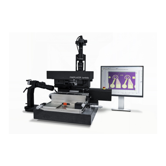
- Page 1 FINEPLACER lambda ® Sub-Micron Bonding System Operator’s Manual Finetech GmbH & Co. KG Boxberger Str. 14 12681 Berlin Service +49 (0) 30 93 66 81-350 Fax +49 (0) 30 93 66 81-144 service@finetech.de All specifications and characteristics are subject to change without notice.
-
Page 2: Table Of Contents
FINEPLACER ® lambda Content Page Content Page INTS FOR SING THIS ANUAL PERATING NSTRUCTIONS ENERAL NFORMATION ON LACER ONTROL FINEPLACER® S 3.4.1 S YSTEMS AND THIS WITCHING ON 3.4.2 C ANUAL ONTROLLING THE RIGHTNESS 3.4.3 U PPLICATION OF THE NDERSTANDING THE ACUUM FINEPLACER®... - Page 3 FINEPLACER lambda ® AINTENANCE REVENTIVE AINTENANCE 6.1.1 M AINTENANCE UTY OF CARE 6.1.2 P OSITIONING TABLE MAINTENANCE POSITION 6.1.3 D AILY 6.1.4 M ONTHLY 6.1.5 E VERY ONTHS 6.1.6 Y EARLY ORRECTIVE AINTENANCE ECHNICAL Rev-Nr. 1.1...
-
Page 4: Hints For Using This
FINEPLACER ® lambda 1 Hints for Using this Manual Please read the safety instructions first before operating the FINEPLACER ® • Have a look at the pictures before reading the operating instructions to familiarize yourself with the FINEPLACER ® . Start with the basic machine and do the same with each module belonging to your special system configuration. - Page 5 FINEPLACER lambda ® Optional accessories include special optics for positioning large fine pitch devices on their substrates and high magnification systems for observing chip bonding. All state of the art bonding technologies can be performed, such as thermocompression, ultrasonic/thermosonic bonding, ACF bonding, UV cure and bonding of C4 chips. Due to the modular system, the necessary configuration may easily be optimized, corresponding to your individual requirements.
-
Page 6: Operating Principle Working And System
FINEPLACER lambda ® 2.2 Operating Principle, Method of Working and System Features The patented advanced Vision Alignment System of the lambda is based on the principle of imaging two orthogonal images simultaneously into one common image plane, using a stationary beam splitter (30) and a single beam deflection (see fig. 1): Fig. -
Page 7: Method Of Working And Placement
® equipment is designed to be used solely for work on components and substrates in the way intended in a configuration agreed with Finetech and together with Finetech approved equipment. In other cases it must be expressly agreed in writing with Finetech GmbH, Berlin, Germany, under the conditions stated in the manual. -
Page 8: General Safetyi
Commercial damage or personal injury caused by neglecting the above safety measures is not covered by Finetech's responsibility. Arrange cables and hoses so that nobody can get caught. If you want to move the machine, first disconnect all cables and hoses and take the positioning table off the base plate. -
Page 9: Safety Regarding E Mains Power
FINEPLACER lambda ® Two-handed handling of the positioning table Under no cirscumstances press the pedal unless both hands are on the positioning table. Risk of damage or injury. With activated air cushion, the positioning table’s outer edges can be moved beyond the edges of the base plate. -
Page 10: Heat And Fire Hazards Burns
EC Directive of Electromagnetic Compatibility (EMC). Magnetic fields being beyond the limits of the above directive could anyhow influence the function of Finetech heating modules resulting in temperature deviation or unexpected program stops. 2.8 Heat and Fire Hazards, Risk of Burns Heating plates and other heating accessories may cause heat and fire hazards by improper use and in the case of equipment defects. -
Page 11: Conditions Of Work
FINEPLACER ® lambda If there is any sign of increasing overheating (if display shows values much higher than set value, or heating period is longer than programmed, or ERROR light comes on etc.), switch off the equipment and call for qualified maintenance personnel! Heating should be stopped in case of danger caused by any heated modules. - Page 12 6000 mg/m³ • Oil content 5 mg/m³ • Comply with the special safety conditions given with the descriptions of the modules. With the Finetech Bonding Force Applicators in particular, beware of bruising fingers or damaging the work piece. Rev-Nr. 1.1...
-
Page 13: The Fineplacer® S
FINEPLACER lambda ® 3 The FINEPLACER System ® 3.1 Introduction Like every FINEPLACER ® , the lambda has been designed for versatile use and ease of operation and maintenance, and is made up of functional modules. The operator should thoroughly understand the function and control of each module and tool in the system before using it. - Page 14 FINEPLACER ® lambda The base plate rests on foot screws which are used to level it. Foot screw at base plate Align the base plate in a way that it slightly slopes backwards, away from the operator. The incline should be between 0.1 mm/m and 0.3 mm/m. Use a circular level for alignment.
- Page 15 FINEPLACER lambda ® Table movement direction with activated air cushion It is strictly prohibited to work with the machine before this setting has been made! 3.2.1.2 The Height Adjustable Positioning Table • ... rests on the base plate (70). It carries the height adjustable tracks used to clamp in a substrate, a substrate support plate or a FINEPLACER ®...
-
Page 16: Support Arm
FINEPLACER lambda ® 3.2.2 Support Arm (71), holding the following parts: • Vision/observation devices, basically consisting of the stationary mounted beam splitter optics (30), providing the dual image overlay, and a video option for vertical view, are used to view the super-imposed image of the substrate's pads and the corresponding component leads. -
Page 17: Placer Control Box
FINEPLACER ® lambda Magnetic interlock Optics shifting in working position (each Optics shifting in swivel position. Pivot arm position apart from swivel position). Pivot can be swivelled down. arm cannot be swivelled down. 3.2.4 Placer Control Box The Placer Control Box is an essential part of any FINEPLACER ... - Page 18 • locking electromagnet control • Target Finder control 5. camera control and power supply for options 6. RS 232 interface 7. Finetech Module Interface (FMI) for connecting Finetech modules 3.3 Short Description of Basic Functions and Directions For Installation 3.3.1 Mains Connection The Placer Control Box has to be connected to the mains via the POWER IN plug in the rear panel of the box using the supplied cable.
-
Page 19: Generation Andc
FINEPLACER lambda ® The light intensity can be used because the light of head and target is balanced by an optical shutter. For further information, refer to the operating instructions (see below). 3.3.3 Generation And Connection Of Vacuum And Compressed Air The built in vacuum pump operates permanently as soon as the Placer Control Box is switched on. - Page 20 FINEPLACER lambda ® 3.3.6 RS-232 Interface The Placer Control Box possesses an RS 232 interface, its connector PC RS-232 is in the back panel. It can be used for linking the PC to the Placer Control Box, allowing modifications of the internal software, as well as communication between the PC and every module connected to the placer Control Box.
-
Page 21: Operating Instructionsf
PC RS232 Connecting PC and Interface Module For this connect all Finetech® boxes in a chain as shown in the picture above. Begin with the Placer Control Box and connect all further module boxes with the delivered interface cables (Western Plug) in any order. Please note that the last box in the chain must be terminated by the terminal resistor plug. -
Page 22: Ontrolling The Brightness
FINEPLACER ® lambda 3.4.2 Controlling the Brightness The revolution transmitters have no mechanical stops at their end positions. Turning the knob clockwise will increase the brightness, turning counter clockwise will decrease it. As soon as the brightness is at its maximum or minimum, a signal is heard. -
Page 23: Parts , Controls Andi
FINEPLACER lambda ® When the arm is in the horizontal position, it is possible to switch the vacuum to the pipette permanently. To do this, the vacuum foot switch has to be pressed for longer then three seconds. 3.4.4 Vacuum Control Safety System The Vacuum Control Safety System minimizes the possibility of component loss caused by faulty operation. - Page 24 FINEPLACER ® lambda Zoom Used to view alignment of component and substrate and to adjust FINEPLACER placement accuracy ® Parallelism fine adjustment screw Rotates the tool around the x-axis to compensate an angular deviation between tool and working plain Locking screws Locking screws for the parallelism adjust (19) Placement head Fits into head receiver (25) and is locked with screw...
- Page 25 FINEPLACER lambda ® "AUTO" Vacuum can be switched over from the placement head (20) to the pipette (24) by pressing the pipette slightly on the body of the component to catch it "EXT" Vacuum can be switched by an additional switch, e.g. a foot switch, connected to socket (65) x micrometer screw Acts as a handle to position x-y positioning table (29)
- Page 26 Connection for the Module Interface Bus (special cable supplied), which provides the communication between all Control Boxes of further modules and the PC within a Finetech System. The last Control Box at the end of this bus must be terminated with a terminal resistor plug. Rev-Nr. 1.1...
-
Page 27: Instructions For Nitial Etp Of The Fineplacer
For FINEPLACER ® lambda, different TABLE 3 FINEPLACER® lambda objective lenses are available. E.g. field diameter in case of insufficient image, first compare the S/N of the Finetech 0,55mm 0,45mm with the delivery note entry. 6,7mm 5,4mm 0,18mm 0,14mm ø 1.25 mm... -
Page 28: Nterconnection Of The Lambda
FINEPLACER lambda ® • Whatever you clamp into the tracks, its upper side's edges must be pressed against the upper edge of the V-slots. • To meet the working plane with substrates placed on a heating plate or on a substrate support plate, the positioning table has tracks that are continuously adjustable for substrate thickness from 0 to 10 mm. -
Page 29: Reliminary Settings And Checkout
FINEPLACER lambda ® • If available, connect the vacuum pipette (24) to the VACUUM PICKUP socket (61), at the front of the Placer Control Box (39). • First connect the power cord with the Placer Control Box socket (62f) and then into the appropriate AC power source. -
Page 30: Equired Tools
FINEPLACER lambda ® 4.2.1 Required Tools: • Finetech Adjustment Set for the pivot arm, resolution 1 µm, consists of a support plate, accuracy adjustment head and a set of Bottom Glass Top Glass Scale glass scales (top and bottom scale); see table 4 at the end of chapter 4.2. - Page 31 FINEPLACER lambda ® 1. Plug the tool into the placer arm The tool needs to be plugged in all the way to the limit stop. 2. Clamp the placement plate with nonius into the table Make sure the plate is securely clamped and free of play. 3.
- Page 32 FINEPLACER lambda ® 4. Pick up the nonius Align the center of the nonius glass to the middle of the field of view using a large magnification. Turn off the vacuum on the placer arm using the foot switch. Select a low force at the Bonding Force Module. Pick up the nonius.
- Page 33 FINEPLACER lambda ® 5. Place up the nonius After the placement you will see that the structure is not in back focus. Remember the z height of the xyz-table and bring the structure into back focus to check the placement accuracy. Make a screen shot if the placement accuracy is not within specification.
- Page 34 FINEPLACER lambda ® 6. Adjusting the Beam Splitter Reproduce the placement error as seen on the screen shot by using the Allen key. This compensates the offset / placement error at hand. Adjust the x offset Adjust the y offset Adjust the nonius overlay again with the y-x-micrometer screws Rev-Nr.
- Page 35 FINEPLACER lambda ® Repeat the placement and check the placement accuracy. If you are still out of specification, repeat the steps. Available Adjustment Set AJ3.P2 Adjustment Set, 1 µm for placement arm with fine rotation Top: Optimal alignment in x direction Right: Optimal alignment in y direction 4.3 Adjusting the Placement Arm's Coplanarity 1.
- Page 36 FINEPLACER lambda ® four pin tool adjustment plate 6. Check the parallelism by using a 50 µm spacer or a light reflection that can be viewed through a gap under one or more legs (all four legs need to be in contact with the plate).
- Page 37 FINEPLACER lambda ® 9. Double check the orientation by using the parallelism adjustment tool with a spacer or reflecting light, as described under 6. 10. As soon as the orientation is adjusted, tighten the fixing screws on the back side. 11.
-
Page 38: Operating Instructions
FINEPLACER lambda ® 5 Operating Instructions The following instructions assume that you are informed and fully aware of the function of the equipment (see chapter 3) and of the safety instructions (see chapter 2) and that the FINEPLACER ® has been calibrated and checked out (see chapter 4.2). -
Page 39: Placement
FINEPLACER lambda ® 5.2 Loading the component for Placement Align the component, lying e.g. face-down in a tray, with the placement head. Then switch off the vacuum, lay down the arm, switch on the vacuum again and pick up the component with the head. See chapter 3.2.4, for information on vacuum control. -
Page 40: Maintenance
FINEPLACER lambda ® 6 Maintenance 6.1 Preventive Maintenance 6.1.1 Maintenance - Duty of care • Maintenance work should only be carried out by trained personnel • Make sure that the machine is in a state where you cannot injure yourself: Substrate Heating Modules and Chip Heating Modules must be deactivated and cooled off, the positioning table has to be in a maintenance position. -
Page 41: Daily
FINEPLACER ® lambda Left-hand maintenance position of the table • Move the positioning table away from the operator towards the arm support and then to the right. This time, the magnet inside the base plate will remain covered by the table (see illustration). Turn off the machine. Clean the left side of the base plate. -
Page 42: Monthly
FINEPLACER ® lambda • Take care of the optical parts. Keep the optical surfaces clean at all times. Glass surfaces of the beam splitter (30) and other optics may be cleaned with customary optics hair pencils or cleaning rags, surface mirrors with alcohol and hair pencil. -
Page 43: Yearly
Finetech for repair or replacement. • Finetech will also help you to identify the fault and give advice if you want to carry out repairs yourself. • Before dismantling defective parts, please contact Finetech or your repre- sentative! •... -
Page 44: Technical Data
Mains Voltage Out, max 10A load - FUSE Mains Fuse, Placer Control Box - MODULE INTERFACE RJ-45 Socket, FMI Bus (Finetech Module Interface) - PC RS-232 9 pin SUB-D Socket Serial Interface to PC - PIPETTE FOOT SWITCH 3 pin Socket... - Page 45 FINEPLACER lambda ® - OPTION OUTPUT, CAMERA I, CAMERA II Sockets Output 12V DC, max. 12W/outlet, max. 24W collective load - ILLUMINATION CONTROL 3 pin Socket Control Voltage Cold Light - TABLE AIR OUT Table Air Outlet - HEAD VACUUM OUT Arm Vacuum Outlet - PIPETTE Pipette Connector...
Need help?
Do you have a question about the FINEPLACER lambda and is the answer not in the manual?
Questions and answers