
Related Manuals for D&V Electronics CDT-65A

Summary of Contents for D&V Electronics CDT-65A
- Page 1 CDT-65A Diode Tester Operations Manual Revision 3.0 (26 July 2010) D&V Electronics Ltd. 130 Zenway Blvd. Woodbridge, Ontario Canada L4H 2Y7 Tel: (905) 264-7646 Fax: (905) 246-0502...
-
Page 2: Table Of Contents
Special Setup Mode Break Over Voltage Current Pulse Width Trio Test Current Rectifier Test Current Calibration 10.0 Restore/Initialize Default Values 11.0 General Reference Information 12.0 Replacement parts 13.0 Replacing Fuses 14.0 Warranty 15.0 Contact Information Operations Manual: CDT-65A Diode Tester Page 1... -
Page 3: Safety Requirements
(grounding) pin. This plug will only fit into a grounding-type power outlet. This is a safety feature. If you are unable to insert the plug into the outlet, contact your electrician to replace your obsolete outlet. Do not defeat the safety purpose of the grounding-type plug. Operations Manual: CDT-65A Diode Tester Page 2... - Page 4 Unauthorized substitutions may result in fire, electric shock, or other hazards. Q. Heat: The product should be situated away from heat sources such as radiators, heat registers, stoves or other products that produce heat. Operations Manual: CDT-65A Diode Tester Page 3...
-
Page 5: Tester Description
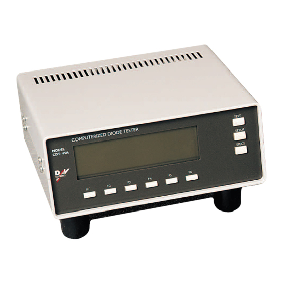
1.0 Tester Description Front View of Tester Control LCD Display Keys Function Keys Rear View of Tester Power Switch Test Lead Printer Port Connection Operations Manual: CDT-65A Diode Tester Page 4... -
Page 6: Electrical Power Requirements
Test current up to 125 Amps Diode voltage drop 1% ± .002V Weight 5 kg Dimensions 28x20x10 cm Operating Temperature: +10 to + 40 C Relative Humidity: 80% Maximum CE certified. Operations Manual: CDT-65A Diode Tester Page 5... -
Page 7: Diode Control Map
DIODE VOLTAGE DROP MIN: DIODE VOLTAGE DROP MAX: LEAKAGE CURRENT MAX: F4 RECTIFIER D (Spec. settings) BREAKOVER VOLTAGE MIN: BREAKOVER VOLTAGE MAX: DIODE VOLTAGE DROP MIN: DIODE VOLTAGE DROP MAX: LEAKAGE CURRENT MAX: Operations Manual: CDT-65A Diode Tester Page 6... - Page 8 F1 Calibrate Breakover Voltage F2 Calibrate Leakage Current F3 Calibrate Voltage Drop F4 Display Calibration Report F5 Print Calibration Report F6 Set Default Scale SETTING DEFAULT VALUES Writing Default Machine Setup… Writing Default Calibration Record… Operations Manual: CDT-65A Diode Tester Page 7...
-
Page 9: Terminology Used With Cdt-65A
A diode with a shorted circuit can allow current to pass in both directions. 1 microamp = .000001 Amp (1000 A = 1mA), CDT65A measures Microamp (A): microamps Milliamp (mA): 1 milliamp = .001 Amp, Operations Manual: CDT-65A Diode Tester Page 8... -
Page 10: Test Instructions
If the TRIO B (F2) button is pressed, programmed, and saved then the corresponding TRIO B (F2) button available in TEST mode will use the limits stored in SPECS mode. Operations Manual: CDT-65A Diode Tester Page 9... - Page 11 To test diodes the operator must have the information from the following table programmed into the tester. The operator can change these settings quickly and easily. These settings can be tailored to meet the specific needs of the diode. Operations Manual: CDT-65A Diode Tester Page 10...
-
Page 12: Sample Test Spec Table
Operations Manual: CDT-65A Diode Tester Page 11... - Page 13 Two beeps indicate the diode has passed and the leads are reversed in reference to the diode’s polarity. The tester will automatically switch the connections internally to compensate for reversed test leads if the REVERSE function is enabled in the setup mode. Operations Manual: CDT-65A Diode Tester Page 12...
-
Page 14: Setup Mode Functions
At the top of the setup screen the number of passed and failed diodes since last power up or reset is displayed. CDT-65A Statistical Report Time:………. Date:……… Current Test Mode Diodes PASS Diodes FAIL Diodes Tested Tested by:………………………………………… Operations Manual: CDT-65A Diode Tester Page 13... -
Page 15: Reset
Vdrop= _._ _ _V REVERSE The CDT-65A will automatically switch the test leads internally if the test leads are reversed if the REVERSE function is enabled. When REVERSE is disabled it is not possible to test a diode if the test leads are reversed, this is useful for sorting diodes by polarity. The REVERSE function is off when there is an X through its icon. -
Page 16: Test Specifications
WARNING: Disconnect the test leads when executing Self Test function. The CDT-65A has a built in self-test feature. The high voltage and high current circuits are both tested and a pass or fail message will be displayed. To run the self- test turn the tester off…... -
Page 17: Machine Setup
The amount of current used to test rectifier diodes can be adjusted from 20 to125 Amps. Use the corresponding up and down function keys to increase or decrease the current. Press Next (F6) to write the setup into the memory. Operations Manual: CDT-65A Diode Tester Page 16... -
Page 18: Calibration
To exit and a save the calibration press TEST, SETUP, or SPECS. A sample calibration report is below: CDT-65A CALIBRATION REPORT No: ..Time: ..Date: .. -
Page 19: Restore/Initialize Default Values
SIGNATURE: ........10.0 Setting Default Values The CDT-65A tester has default test and calibration values stored in its memory. To initialize or restore these values press and hold F4 and turn the power on. When these values have been restored or initialized the tester should be calibrated. -
Page 20: Replacing Fuses
13.0 Replacing the Fuses Replace with 2 x 250V/1A Fuses only. Operations Manual: CDT-65A Diode Tester Page 19... -
Page 21: Warranty
If D&V elects to perform any such services at customer’s request, then such services will be deemed a service call and all labor, parts and materials used for the service call will be charged at D&V’s then-prevailing rates. Operations Manual: CDT-65A Diode Tester Page 20... - Page 22 D&V’ expense. If after reasonable opportunity D&V is unable to re-perform such services to the reasonable satisfaction of customer, customer may, as its exclusive remedy, obtain a refund of the fees paid to D&V under the applicable order for such services. Operations Manual: CDT-65A Diode Tester Page 21...
-
Page 23: Contact Information
THE ACTUAL AMOUNTS RECEIVED BY D&V FOR THE SPECIFIC PRODUCT WITH RESPECT TO WHICH SUCH CLAIM IS MADE. GOVERNING LAW AND JURISDICTION 15.0 Contact Information Head Office D&V Electronics Ltd. 130 Zenway Blvd Woodbridge, Ontario Canada, L4H 2Y7 001 905 264-7646 www.dvelectronics.com Technical Support dvsupport@dvelectronics.com Operations Manual: CDT-65A Diode Tester Page 22...
Need help?
Do you have a question about the CDT-65A and is the answer not in the manual?
Questions and answers