Table of Contents
Advertisement
Quick Links
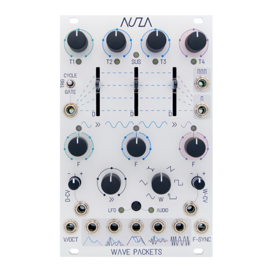
WAVE PACKETS
PANEL OVERVIEW
The toggle switch position is used to determine the excitation mode (in conjuction
with the presence of a cable in the
TRIGGER
This input is used to excite a wave packet. The presence of a cable in this
input is also used in conjunction with the
EXCITATION MODE SWITCH
to set the excitation mode. Refer to MODES on p.4.
The 3 sliders draw out a contour function (linear segments from each T stage to
the next), also referred to as the 'minimal contour line'.
The glide control determines the fluidity of change in the 3
glide at the counterclockwise position, turning the knob clockwise will progressively
increase the width of the transition time about the T1/T2 and T3/T4 stage
boundaries, with a linear-sounding glide always ensured.
CV Input with attenuverter for
D
(depth) parameter. Adds or subtracts to each of
CV input (1V per octave) modulation of oscillator frequency - a global frequency
shift to the entire wave packet. If in AUDIO frequency mode, plugging a cable in
to V/OCT will semitone-quantise the frequency selection on the 3
If
F-SYNC
is also used, V/OCT will modulate at 1V per octave from the
frequency (plus the pitch offsets added to this from the 3
5 main outputs (3 unipolar and 2 bipolar). Output 1 (leftmost) provides a direct
feed from the contour function, output 5 (rightmost) provides a direct feed from
the oscillator, and the remaining 3 outputs use the contour function to sculpt the
oscillator output in to various wave packet forms. Refer to the outputs
Wave Packets is a multi-talented complex modulation and audio source. The module allows you to craft 'wave packets', with each of
the 5 main outputs deploying a different recipe from the contour function (linear segments between each time stage) and frequency-
dynamic oscillator (LFO or audio-rate oscillation which transitions through 3 target frequencies) to produce a unique modulation shape,
burst of energy, or fragment of audio.
Times for the 4 T stages. Max time is 10s, and min time
is 0s (completely skipping the stage). If in CYCLE-PING
excitation mode or LINKED LFO mode, the T knobs have a
different functionality (refer to MODES on p.4/ p.5).
INPUT). Refer to MODES on p.4.
above it
F
frequencies. With no
the 3
D
slider positions.
F
knobs.
F-SYNC
F
knobs).
Tapping the button will toggle between LFO and AUDIO frequency modes, with the respective LED lighting to indicate the chosen mode.
Additional Modes/ Shift Parameters Access:
- Holding down the button for 3s while in LFO frequency mode will toggle LINKED LFO mode on and off.
- Holding down the button while toggling the
- Holding down the button while moving the
description on p.3.
- Holding down the button while moving the
The module's oscillator traverses through 3 target frequencies during the course of
a wave packet, represented on the module panel from left to right with 3 colours:
green (T1), blue (T2, SUS, T3) and purple (T4).
- In LFO frequency mode, the 3
each centred at 4 Hz and spanning 5 octaves either side. Each LED above the 3
F
knobs flashes a sine wave pattern at the corresponding rate.
- In AUDIO frequency mode, the middle (blue)
centred on note C3 and spanning ±5 octaves, and the left and right
starting/ ending ± pitch offsets to the middle base frequency. Therefore a
frequency transition profile similar to a pitch envelope can be constructed,
trackable in pitch using V/OCT. The 3 LEDs represent frequency using a colour
spectrum, and show the relationship between the 3
Waveform shape of the oscillator, with continuous morphing in between the 6
main shapes.
CV Input with attenuverter for
W
knob position.
A tempo/ clock signal, LFO or audio oscillator output (primitive waveform shapes
only) can be plugged in to this input to clock in the oscillator frequency. In LFO
Frequency Mode, the 3
F
multipliers to the F-SYNC clock rate. In AUDIO frequency mode, the 'base'
frequency of the wave packet will be set by F-SYNC plus a pitch offset to the
F-SYNC frequency set by the middle
knobs add starting/ ending pitch offsets to the base frequency.
EXCITATION MODE SWITCH
to the up (CYCLE) position will activate CYCLE-PING excitation mode.
>>
(glide) knob will change the oscillator phase in 90° increments (along the knob 'dot' markings).
W
(wave) knob fully clockwise or counterclockwise will change the saw wave shape direction.
Trigger output at end of each stage
Trigger output at end of a full wave packet cycle
F
knobs operate as 3 independent rate controls,
F
knob sets the 'base' frequency,
F
knobs set
F
knobs.
W
(wave) parameter. Adds or subtracts to the
knobs will then function as individual clock dividers/
F
knob. Like before, the left and right
F
Advertisement
Table of Contents

Summary of Contents for AUZA WAVE PACKETS
- Page 1 Wave Packets is a multi-talented complex modulation and audio source. The module allows you to craft 'wave packets', with each of WAVE PACKETS the 5 main outputs deploying a different recipe from the contour function (linear segments between each time stage) and frequency- dynamic oscillator (LFO or audio-rate oscillation which transitions through 3 target frequencies) to produce a unique modulation shape, burst of energy, or fragment of audio.
- Page 2 C3, with the left and right knobs providing starting/ ending ± pitch offsets to the middle base frequency. Common to every manner of using Wave Packets are the stages. As well as determining the overall duration of LFO Mode: 3 independent rates...
- Page 3 Wave Packets will track instantaneously to an external audio oscillator, the contour function. As the signal is not enveloped, anti- mimicking its frequency characteric with no audible jumps as the frequency changes.
- Page 4 CYCLE position. CYCLE-PING CYCLE The cycle of wave packets will then start immediately on the second detected pulse, and the T1 LED will Hold down the BUTTON while flicking the GATE oscillate in the meantime to denote that pulses are pending.
- Page 5 The 3 F LEDs are yellow when LINKED LFO mode is OFF: audio source. Wave Packets will also adapt its behaviour in a number of other ways to optimise the intended use. All of the differences (many also discussed elsewhere in the manual) are summarised below.
- Page 6 DIAGRAMMATIC MODEL OVERVIEW...
- Page 7 Return shipping is to be paid by the customer and the choice of repair or replacement is to be solely determined by Auza upon 270°...
Need help?
Do you have a question about the WAVE PACKETS and is the answer not in the manual?
Questions and answers