Table of Contents
Advertisement
Quick Links
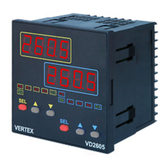
INSTRUCTION MANUAL FOR VD2605 LOW COST DUAL
■ FRONT PANEL DESCRIPTION :
(1)
SET KEY. Press once to access the next programmable parameter. press for 5 seconds to
(2)
UP KEY. Press to increase the set point or parameter value.
(3)
DOWN KEY. Press to decrease the set point or parameter value.
(4)
Press the SET and UP keys once to return to normal Process Value display.
(5)
+
Press the SET and DOWN keys simultaneously for 5 seconds to access "LnLo" and
■PANEL CUTOUT:
A
Model
A
VD-2605
48
CHANNEL CONTROLLER/INDICATOR
( (1)PV - Process Value/Parameter indicator
(2)SV - Setting Value indicator
(3)C1 - Control output status indicator
(4)A1 - Alarm 1 output status indicator
(5)A2 - Alarm 2 output status indicator
(6)A3 - Alarm 3 output status indicator
move from one programming level to next.
"LnHi" parameters.
B
B
C
48
6
D
E
a
100
45
45+0.5
b
c
45+0.5
60
48
(Unit:mm)
d
Advertisement
Table of Contents

Summary of Contents for GOLINK VD2605
- Page 1 INSTRUCTION MANUAL FOR VD2605 LOW COST DUAL CHANNEL CONTROLLER/INDICATOR ■ FRONT PANEL DESCRIPTION : ( (1)PV - Process Value/Parameter indicator (2)SV - Setting Value indicator (3)C1 - Control output status indicator (4)A1 - Alarm 1 output status indicator (5)A2 - Alarm 2 output status indicator (6)A3 -...
- Page 2 ■ WIRING DIAGRAM: Wiring Precautions: 1.Before wiring, verify the controller label for correct model number and option. 2. For thermocouple input, use the appropriate compensation wire. And note the polarity of input signal. 3.To avoid noise induction, keep input signal wire away from instrument power line, load lines and power lines of other electric equipment.
- Page 3 ■ PROGRAMMING LEVEL PARAMETERS lst. Prog. Level 2nd. Prog. Level 3rd. Prog. Level Press 5 seconds Press 5 seconds /Press 5 seconds parameters will be ≠ 0.0. and available only when will be skipped. parameters will be available only when = t.on or t.Off.
- Page 4 FIRST PROGRAMMING LEVEL PARAMETERS(USER LEVEL) CODE DESCRIPTION RANGE DEFAULT LoLt - HiLt Set point value of control Set point offset. : Offset (manual reset) value for P -1000-1000 (-100.0-100.0) control only. Process value offset.:use to offset the PV indication -1000-2000 (-100.0-200.0) from the actual PV Alarm 1 setting value...
- Page 5 THIRD PROGRAMMING LEVEL PARAMETERS(OPTION LEVEL) CODE DESCRIPTION RANGE DEFAULT Input type selection. RANGE(℃) RANGE(℉) TYPE -50 ~ 1000 -58 ~ 1832 -50 ~ 1370 -58 ~ 2498 -270 ~ 400 -454 ~ 752 -50 ~ 750 -58 ~ 1382 0 ~ 1800 32 ~...
- Page 6 nonE, Stdy, Alarm 3 mode. Refer to alarm mode section for detail. Lath, St.La HH.mm, mm.SS Address of controller when communication with 0-255 master device. Communication baud rate. 2.4k=2400bps, 4.8k=4800 2.4k, 4.8k, 9.6k bps, 9.6k=9600 bps, 19.2k=19200 bps 9.6k, 19.2k Scaling for Linear Input 1.
- Page 7 ALARM MODE ALMD DESCRIPTION Normal alarm mode Standby mode When selected, in any alarm function, prevents an alarm on power on. The alarm is enabled only when the process value reach alarm set point. Also known as “Startup inhibit” and is useful for avoiding alarm trips during startup. Latch mode.
Need help?
Do you have a question about the VD2605 and is the answer not in the manual?
Questions and answers