Table of Contents
Advertisement
Quick Links
Advertisement
Table of Contents

Summary of Contents for GRANDEG TURBO Series
-
Page 2: Table Of Contents
Operation Installation Manual before installing and operating your boiler. Please remember, that your boiler must be commissioned GRANDEG certified service specialist. Failure to observe the guidelines set out in this Operation and Installation Manual may invalidate your warranty. -
Page 3: Introduction
In order for the GRANDEG boiler to serve for a long time and reliably, the following three conditions have to be met: 1) follow the terms defining proper operation of the boiler;... -
Page 4: General Information
(lambda probe), precisely regulates the amount of air necessary for efficient and economic combustion of different wood and biomass pellets. Turbo series pellet heating boilers with output of 200, 300 and 500kw are equipped with ladder for convenient access to vertical heat exchanger tubes during maintenance. -
Page 5: Turbo Pellet Heating Boiler Components
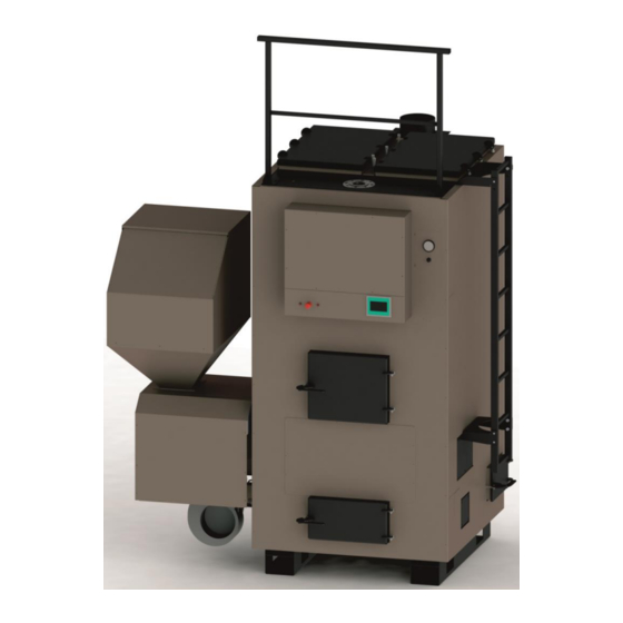
Turbo Pellet Heating Boiler Components This pellet heating boiler consists of 2 parts – a water heating boiler and a pellet hopper. Boiler body (1) is a welded construction made of high quality 4-6 mm thick steel sheets. Boiler body is covered with removable decorative siding with heat insulation underneath. -
Page 6: Turbo Pellet Heating Boiler Key Features
Designations: Boiler body Connection flange for pellet supply mechanism Heat exchanger cleaning Connection flange for combustion (air) fan doors Decorative siding Flue pipe cleaning hatch Ash compartment cleaning Thermo manometer door (front) Connections to the heating Connection flange for pellet supply mechanism system combustion (air) fan and motor Boiler flue starting collar... - Page 7 Two-step Pellet Supply Mechanism A two-step pellet supply mechanism is located directly beneath the pellet hopper. It consists of a rotary airlock and pellet dosating valve and a screw feeder, which transports pellets further into the pellet burning area. Rotary airlock and pellet dosating valve ensures an equable and smooth dosage of pellets and protects against potential back burn and smoldering in the pellet hopper.
-
Page 8: Safety Guidelines
Safety Guidelines GRANDEG Turbo pellet heating boiler is specially designed thinking about user/operator safety. However, GRANDEG reminds that certain safety guidelines still must be observed during operation of any heating boiler. Safety guidelines set out below will help avoid hazardous situations and ensure a long operational life for your pellet heating boiler. - Page 9 b. Safety Information for Moving and Transporting the Pellet Heating Boiler Be cautious when moving or lifting the pellet heating boiler or pellet hopper – these objects are heavy and may cause injury. Use appropriate lifting techniques and equipment. Make sure that exterior of the boiler is not damaged while lifting.
- Page 10 It is forbidden to install a valve between the boiler and safety valve as well as between the boiler and expansion vessel. Before planning any changes to heating boiler equipment or the layout of the boiler house, it is recommended to consult a certified service specialist about compliance of planned changes.
- Page 11 Always place ash in metal container (i.e., ash pan) to avoid fire outburst. Lower quality pellets will require more frequent boiler cleaning and maintenance. If you change your pellet supplier, GRANDEG recommends that you contact your installer to check, if adjustment of burner operation settings in the boiler control system is necessary.
-
Page 12: Signage On The Boiler
GRANDEG certified service specialist. It is required to call out a GRANDEG certified service specialist for boiler maintenance once a year, preferably at the end of heating season. Cleaning of chimney should also be performed by a specialist before or after the heating season. - Page 13 Max. pressure allowance for the heat carrier (water) in the boiler Electromechanical (stopping electricity supply) thermoprotection switch for protection against overheating of the heat carrier (water) Valve for regulating air overpressure in the pellet supply mechanism Valve for regulating combustion air supply Oxygen analyzer during combustion process (lambda probe) Max.
- Page 14 Location of doors for cleaning heat exchanger tubes Location of hatch for cleaning boiler flue pipe Location of ash removal compartment Warning Signs All doors must be closed during operation of the heating boiler Warning! A corrosion protection system must be installed to ensure the min.
- Page 15 Warning! Moving mechanisms! Warning! Electric power! Warning! Use protective gloves when cleaning the heating boiler Rotation direction of the rotary airlock and pellet dosating valve Ignition element...
-
Page 16: Fuel Recommendations
Good quality fuel may cost more, but in return will result in substantially higher energy efficiency. Poor quality fuel will reduce heating boiler output and speed up boiler wear and tear. Thus, GRANDEG, recommends to pay due attention to the quality of pellets! Please note that boiler repairs due to using poor quality pellets are not covered by warranty. - Page 17 Without protective packaging, pellets may be stored for several months since air humidity has a small effect on them. To ensure optimal and efficient operation of your pellet heating boiler, GRANDEG recommends pellets that meet the following standards: European Union...
-
Page 18: User Information
This section covers the following topics – commissioning of the heating boiler, its operation process and control system as well as maintenance and cleaning. Commissioning In order to maintain your warranty, a GRANDEG certified service specialist should launch and commission your heating boiler. During Commissioning, your certified service specialist should: ... -
Page 19: Boiler Operation Process
Boiler Operation Process GRANDEG pellet heating boiler can be started by pressing ‘Start’ button on the Main screen of the Control panel (Please refer to the Main Screen Description). Overall, the boiler work cycle can be divided into twelve stages. - Page 20 2. After 30 seconds air fan vault is opened and air fan is started at low load, waits 13 minutes until next step 3. Flame presence is determined by lambda probe (oxygen level in flue gases should be less than 80% for at least 5 seconds) Sequence steps indicated on Main screen in Control panel that correspond to current stage of work cycle: Step...
- Page 21 If 3 reigniting attempts are not successful, boiler remains at Ignition stage, generates an alarm and waits for operator command. By pressing Reset button on Alarm screen, operator confirms that boiler should go to next three attempts to reignite. If unsuccessful, press Stop button and call support. Sequence steps indicated on Main screen in Control panel that correspond to current stage of work cycle: Step...
- Page 22 Work cycle. Step 30 Boiler running on set 100% load. Run on 100% load. Work cycle. Boiler running on variable load, Step 31 Variable load according determined automatically PID controller. Waiting 1. Air fan is off, air vault is closed, and screw feeder is off. Boiler waits for temperature decrease.
- Page 23 Cleaning 1 1. Both right and left cleaning bolts are opened. 2. If in 200 seconds open limit switch signals, confirming opening of the bolts, do not appear, control system tries to close and then reopen bolts. If three attempts are unsuccessful, alarm is indicated and boiler waits for operator command.
- Page 24 3. Boiler switches to Cleaning 3 after limit switch signal appears. Sequence steps indicated on Main screen in Control panel that correspond to current stage of work cycle: Step Step description in Full description Info screen Cleaning. Step 11 Left and Right opened 200 second time limit for cleaning stage stay time Cleaning.
- Page 25 Step 18 Empty. Empty Cleaning. Boiler resets screw feeder work time Step 19 Reset work hours counter to zero counter Stop 1. Recirculation pump works for 15 minutes and stops. 2. Boiler is stopped and ready for Start. Sequence steps indicated on Main screen in Control panel that correspond to current stage of work cycle: Step Step description in...
- Page 26 In case of long intervals in between boiler operations during which air temperature in boiler house may drop below 0 0C, the heating system should be provided with alternative heat source. Before planning any changes to heating boiler equipment or the layout of the boiler house, it is recommended to consult a certified service specialist about compliance of planned changes.
- Page 27 Main Screen Description Description/Function Alarm button (Blinks at presence of emergency situations in the system. When pressed, opens Alarm screen (please refer to Alarm screen description) Flue gas temperature and lambda probe Text window with current boiler system information (please refer to the Table below for all options) Current date and time Boiler temperature...
- Page 28 STOP (stops boiler operation) PAUSE (stops boiler operation) RESUME (starts boiler operation after pause) CLEANED (confirms completion of manual cleaning) Info button (switches Main screen to Info screen, please refer to Info screen description) Boiler automatic cleaning bolts and limit switches. The following options are possible: ...
- Page 29 Boiler is controlled remotely (other controller), in auto Remote - Working mode, and running Boiler is controlled remotely (other controller), in auto Remote – Burn out mode, and extinguishing (remaining pellets are used without supplying new ones) Boiler is controlled remotely (other controller), in auto Remote -Cleaning mode, and cleaning (automatic or manual) Boiler is controlled remotely (other controller), in auto...
- Page 30 Exit Info screen User Login/Logout (used only by service personnel) Go to Alarm History (please refer to Alarm history screen description) Go to Historical Data Screen (please refer to Historical data screen description) Export all historical data to flash card Restart button restarts the control panel Alarms Screen Description Description/Function...
- Page 31 Potential Alarms and Solutions List Alarm text Cause Operator response Emergency button is Release emergency stop pressed button Check boiler Emergency stop (Button temperature. After or overheat) temperature has fallen to Boiler has overheated normal, release temperature safety switch Check mechanical bolt Mechanical obstacle, that inside burning chamber.
- Page 32 Bolt is damaged Call support Limit switch is damaged Call support Wait for 5 minutes. If alarm still present, check Boiler is not ready to mechanical bolt inside start, as right cleaning burning chamber. bolt is not closed Remove obstacles. Press Right cleaning not closed Reset button on Alarms screen...
- Page 33 Alarms History Screen Description Description/Function List of all historical emergency and warning alarms. Alarm number, time and date of alarm occurrence, alarm acknowledgement status and explanation text are displayed (please refer to Potential alarms and solutions list) Exit Alarm history screen Go to Alarms screen (please refer to Alarms screen description) Historical Data Screen Description...
- Page 34 Description/Function Go to Alarms screen Graphical representation of system parameters Exit History data screen Current parameter value View a graphical representation of all parameter values over the past 24 hours Browsing parameter data graph - Zoom in Browsing parameter data graph -Zoom out Browsing parameter data graph -Go to Beginning Browsing parameter data graph...
- Page 35 Browsing parameter data graph - Zoom in Browsing parameter data graph -Zoom out Browsing parameter data graph -Go to Beginning Browsing parameter data graph -Go Back OH10 Go to Historical data screen OH11 Browsing parameter data graph -Go Forward OH12 Browsing parameter data graph -Go to End OH13 Browsing parameter data graph...
-
Page 36: Boiler Maintenance
Slag removal stick GRANDEG reminds you that you should take care not only of your pellet heating boiler technical and visual state, but also of the whole heating system, including flue pipes and chimneys. GRANDEG recommends performing cleaning of horizontal parts and bends in flue pipes once a month. - Page 37 Annual maintenance is a chargeable service performed by GRANDEG certified service specialist. Before annual maintenance the user or operator of the pellet heating boiler is required to: ...
-
Page 38: Installation Information
Installation Information This section contains information on the installation requirements for your heating boiler, its dimensions and required clearance from nearby objects, technical data, recommended connection schemes installation process recommendations for flue pipe construction. Installation Requirements Pellet heating boiler must be installed vertically on a smooth, flat, and fire-proof surface or a fire-poof base which exceeds size of the boiler by a minimum of 30 cm in the front and by 10 cm on other sides, according to construction and operation regulations. - Page 39 Boiler Dimensions and Recommended Clearances Boiler ø M Dn 1 Dn 2 Dn H5 Ø60 Ø60 Ø60 GD TURBO 70 1560 1884 1804 2750 (1/2'') (1/2'') (1/2) Ø60 Ø60 Ø60 GD TURBO 100 1875 1615 2185 2104 3000 (1/2'') (1/2'') (1/2) GD TURBO 200 1122...
-
Page 40: Technical Data
Technical data Turbo Series Pellet 70 kW 100 kW 200 kW 300 kW 500 kW Heating Boilers Nominal power, kWh (±10%) 1.1. not less not less not less not less not less Total efficiency factor, % 1.2. than 90 than 90... - Page 41 For biomass pellets Emissions (grams/h), for a properly 0,045 0,064 0,129 0,193 0,322 1.17. set-up and cleaned boiler Level of noise generated by the boiler during its operation, dB, not 1.18. more than 1.19. Voltage, V (50 Hz) Calorific power of wood pellets, 4100 –...
-
Page 42: Recommended Connection Schematics
Recommended Connection Schematics Water Connections Schematic Designations: Water inflow to the heating system Thermostat Water outflow from the heating Safety valve system Water supply to the boiler Ball type valve Water outflow from the boiler Water filter Thermo manometer Sealing plug Thermometer Pump Three way mixing valve... - Page 43 Boiler Control System Connection Schematic Blue Pellet sensor +24V +24V +24V +24V T safety switch +24V Reserve Reserve T Flue gas Pt100 T inside boiler Pt100 +24V +12V Recirculation pump Ignition element 2 Ignition element 1 Right cleaning Left cleaning Secondary air - Damper Secondary air - Ventilator Primary air - Damper...
-
Page 44: Installation Process
It is forbidden to install a valve between the boiler and safety valve as well as between the boiler and expansion vessel. GRANDEG recommends that a certified service specialist performs the installation of your boiler (Please refer to the Recommended Connection... -
Page 45: Recommendations For Flue Pipe Installation
Recommendations for Flue Pipe Installation The pellet heating boiler must be connected to a proper size flue pipe which is insulated and lined. Chimney flue pipe cross-section diameter must be ¼ times bigger than the cross-section diameter of boiler flue starting collar. Choice of flue pipes’... - Page 46 Make sure that your pellet heating boiler flue pipe is not connected to other heating system (appliances), except if constructed for discharge of flue gasses from several heating systems. Designations: Pellet boiler Boiler flue Stainless steel flue pipe that connects Pellet burner boiler flue to the flue pipe system Burning chamber door...
- Page 47 Flue pipe must provide discharge of overpressure from the boiler to secure smooth discharge of the flue gasses. Flue pipe must be equipped with condensate collector. Horizontal parts of flue pipe connections must be equipped with hatches for monitoring and cleaning (10).
-
Page 48: Warranty Terms
Warranty Terms Please note that the Manufacturer cannot be held liable for any direct, indirect or accidental losses (including loss of profit) which may occur as a result of operation, idleness, defects or standstill of its manufactured heating boiler (Product), even if the Manufacturer has been informed about the possibility of occurrence of such losses. - Page 49 For doors and hatches and their fixating parts - if a fracture in the metal and/or a welded joint occurs; For the measurement instruments panel section of the boiler, the three- way valve mechanism - if a fracture and/or a leak in the metal and/or a soldered joint is detected, but only if the assembly is as provided by the manufacturer;...
- Page 50 that the temperature of the heat carrier (water) returning from the heating system of the building is not lower than 60°C. Warranty Receival Terms The Product has been installed in conformity with the recommended water, electricity and flue duct connection schemes that are provided in the Operation and Installation Manual.
- Page 51 The pressure in the heating system must not be lower than 0.5 bar/cm2, and it must not exceed the working pressure of the boiler, which is indicated in the Operation and Installation Manual of the Product. The heating system is of closed type and it is equipped with deaerators so that accumulated air would automatically be drained from the system.
- Page 52 comply with the warranty terms set forth in this Operation and Installation Manual. The Service Specialist must reach agreement with the Client regarding a visiting time to perform repairs. The Service Specialist must visit the Client and repair the damage no later than 48 hours after receiving a verbal or written call by the Client.
- Page 53 Annex No.1 „Annual Maintenance Form” Action OK/Notes Check, whether the boiler house complies with the requirements specified in the Operation and Installation Manual. Check if the water, electrical and flue duct connections of the Product comply with the requirements specified in the Operation and Installation Manual. External/visual diagnostics of the Product: Check the condition of the painting;...
- Page 54 Check the operation of the overpressure safety valve so that it would not leak under 7.3. the foreseen working pressure of the system; Check the technical condition of the shut-off valves (they must not be wet); 7.4. Check the connections of the remaining water pipes and the sealing points of fittings 7.5.
- Page 55 Annex No.2 „Notes on Performed Annual Maintenance” First set-up and commissioning of the boiler: Works performed: Service Specialist: Client: ________________ /_______________/ Date: _________________ Reason for the call: Detected problems: Works performed: Service Specialist: Client: ________________ /_______________/ Date: _________________...
- Page 56 Annex No.3 „Cleaning log for Turbo series pellet heating boiler”...
- Page 57 Date: ___/___/___ _________________________/_____________________/ Signature Signer Warranty Provider Company: SIA “Grandeg serviss” Reg. No: LV44103053549 Contact person: Gatis Rebāns, mob.:+371 26318998 I hereby confirm that the Product is installed, connected and set up in accordance with the Technical requirements of the Product and that the Client is entitled to Warranty Repairs of the Product in accordance with the terms described in the Operation and Installation Manual of the Product.
- Page 58 SIA GRANDEG By presenting this Warranty Certificate, the Client is entitled to demand that the Warranty Provider replace or repair the damaged components without any additional payment, in accordance with the Terms of Warranty that are described in detail in the „Terms of Warranty” section of the Operation and Installation Manual of the Product.
Need help?
Do you have a question about the TURBO Series and is the answer not in the manual?
Questions and answers