Dancutter DC SUPER FLEX Instructions Manual
Hide thumbs
Also See for DC SUPER FLEX:
- Instructions manual (41 pages) ,
- Instruction manual (43 pages)

Related Manuals for Dancutter DC SUPER FLEX

Summary of Contents for Dancutter DC SUPER FLEX
- Page 1 Instructions DC SUPER FLEX Before you take this equipment in enterprise, you must read these operating instructions very carefully. Dancutter a/s Livøvej 1 DK-8800 Viborg P +45 9651 2150 info@dancutter.dk dancutter.com...
-
Page 2: Table Of Contents
Contents 1.0 Manufacture ........................s. 3 2.0 Model Type ........................s. 4 3.0 Safety Instructions ......................s. 4 4.0 Technical Description ....................s. 5 5.0 Service and Maintenance ....................s. 6 6.0 Instructions ........................s. 7 7.0 Hose reel ......................... s. 8 8.0 25M vs 50M ........................ -
Page 3: Manufacture
Technical support Livøvej 1 If you experience problems with the cutter or if you have any DK-8800 Viborg technical questions, please write to support@dancutter.dk Tel: +45 9651 2150 Order info@dancutter.dk If you need spare parts or cutting heads, please write to order@dancutter.dk... -
Page 4: Model Type
Identification: System Type: Mobile cutter unit Model: DC SUPER FLEX 3.0 Safety Instructions • Only start the air sander when the cutter is in the pipeline. • Screws, adapter, cutting tools, etc. must be inspected weekly for wear and damage and must be replaced or tight- •... -
Page 5: Technical Description
Supply hose: 25 m or 50 m Control Unit L: 350mm - B: 300 mm - H: 150 mm Weight: 7 kg, 15.4 lb Power supply: 24VAC In the event of new product developments, Dancutter reserves the right to change the technical description without advance notice. -
Page 6: Service And Maintenance
5.0 Service and Maintenance • Always replace the covers on the Cable, Control Unit after use in order to protect the power connectors. • Be careful with the compressed air line to avoid dirt getting into the air supply. • Avoid water/moisture on the control unit, as it is not splash proof. -
Page 7: Instructions
70 up to 125 mm. Depending on the internal con- camera’s tank (7.5). Slowly lift the cutter arm by moving the dition of the pipe, the DC SUPER FLEX can be passed through joystick (9.3) back towards the operator so that the cutting 90°... -
Page 8: Hose Reel
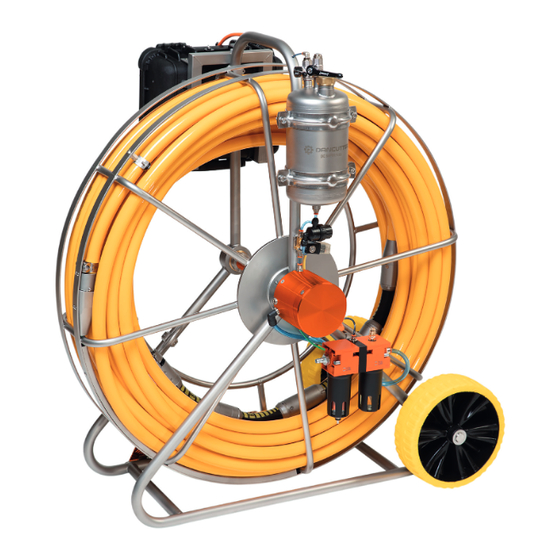
7.0 Hose reel 1. Base plate 2. Filling the washer fluid 3. Camera cleaning 4. Lock and Slip rings house 5. Tap for air to the tank 6. Water separator and oil lubricator 7. Cutter... -
Page 9: Vs 50M
8.0 DC SUPER FLEX 25 M vs. 50 M DC SUPER FLEX 25 DC SUPER FLEX 50... -
Page 10: Cutter
9.0 Cutter 1. Back - forward movement 2. Rotary motor 3. Flexible hose 4. Turning point with built-in slip ring and air and water sluice 5. Camera 6. Camera cleaning 7. Cutting Head 8. Grease... -
Page 11: Control Unit
Control Unit L: 350 mm - B: 300 mm - H: 150 mm Power supply: 110 / 220 VAC Weight: 7 kg In the event of new product developments, Dancutter reserves the right to change the technical description without advance notice. - Page 12 1. FW/BW: use the joystick to operate the cutter’s forward/ for normal operation. Turning the knob to the right makes back movement. the joystick work in reverse. The “arm: up/down” function is unchanged regardless of the switch position. 2. VIDEO OUT: outlet for showing the camera image on an external screen.
- Page 13 Always replace the covers on the CABLE AND CONTROL UNIT after use in order to protect the power connectors. Always hang the Control Unit in its place after use.
-
Page 14: Cutting Tools
Dancutter recommends using the following cutter heads for re-opening of laterals. DK2020-18 DK2629-16 DK3015-16... - Page 15 Dancutter recommends using the following diamond heads for concrete. DKA1022 DD4623 DD3015 Dancutter recommends using the following cutting discs for iron/steel DD9008 DD9023...
-
Page 16: Replacing The Air Motor
12.0 Replacing the Air Motor Raise the arm so that the 5mm Allen key can be inserted and The air motor can then be pulled out and replaced. loosen the screw on both sides (11.1). Install the motor in revers order. 11.1... -
Page 17: Water Separator And Oil Lubricator
13.0 Water Separator and Oil Lubricator Fill oil before using the cutter. REMEMBER, replenishing the air supply, clean the filter if necessary. oil when the top of the oil can be seen in the glass (13.5). It The mist lubricator must not be adjusted, as this has been is important that the glass does not run out of oil, as this will configured at the factory.The mist lubricator must be kept damage... -
Page 18: Installation Of Centring Tool Set W/Brushes
14.0 Installation of centring tool set w/brushes The hollow/recess on the individual half-globes in the centring important for the unit mounted at the rotation point (8.4), as tool set, must ALWAYS face towards the air motor. Were the it would otherwise tighten and prevent the smooth rotation of spotfacings are tapped into the Half-Globes. -
Page 19: Installation Of Centring Tool Set W/Wheels
15.0 Installation of centring tool set w/wheels Air motor Rotary Slip ring Fixed Fixed IMPORTANT! Remove the cover before installing the centring tool set. Slip ring There is a spotfacing on the periphery of each part of the cen- Place the cutter underneath the three centrings rings so that tring tool set. - Page 20 Position the spotfacings one on top of the other. There is a spotfacing on each of the centring rings to indicate which side of the ring should face the air motor. Spotfacing Position the spotfacings facing forwards.
Need help?
Do you have a question about the DC SUPER FLEX and is the answer not in the manual?
Questions and answers